As I mentioned earlier about other parts needed in this upper center section. I apologize for not pointing this out before but in the pictures of the oil cooler saddles, the wing sections are mounted to the fixture upside down. What you are looking at is the underside of the upper wing section. The oil cooler hangs from these mounts.
Ok, here's what is called a support angle and is missing on our aircraft. It is the little box piece in the center of the picture.
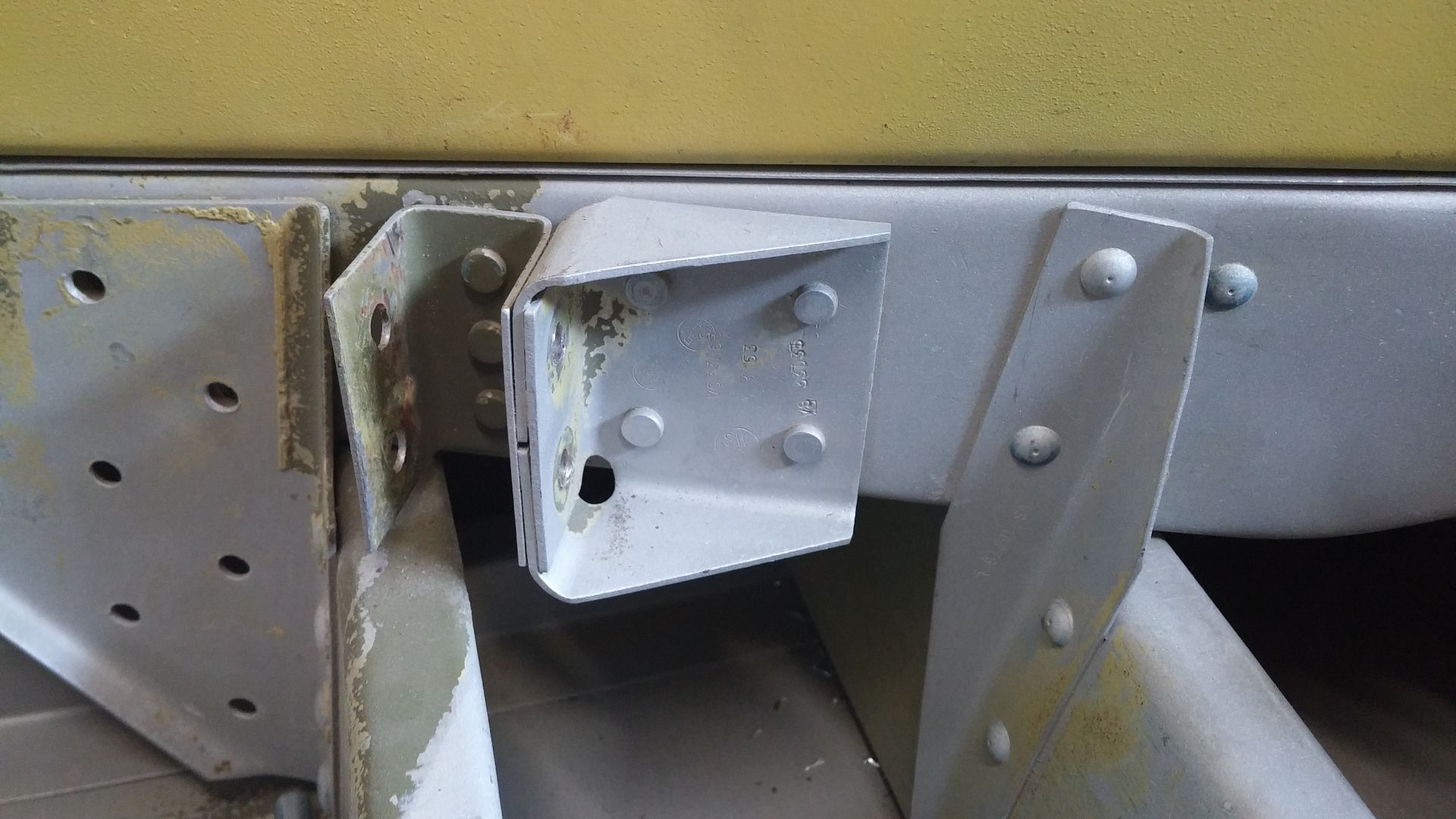
So, as with many of these parts, I still need to figure out how to make them. During the war they had really elaborate forming tools, dies and machines to do these in quantity. I need two. If you look at this piece, there are three folds required with two over-lapping the first. So, it was necessary to mentally unfold the piece to determine a pattern. The original drawings just show the finished part.
So, a paper pattern first and then a template.
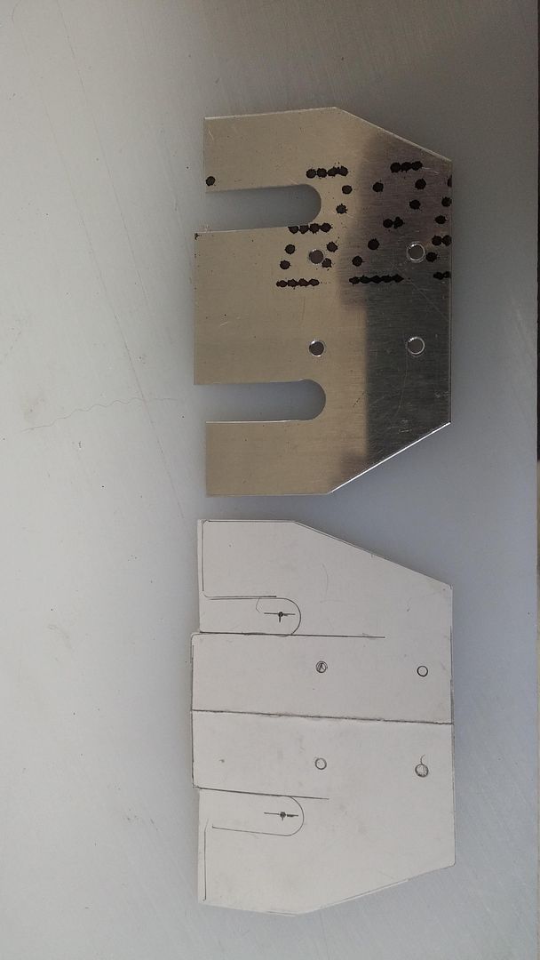
Then the blank.
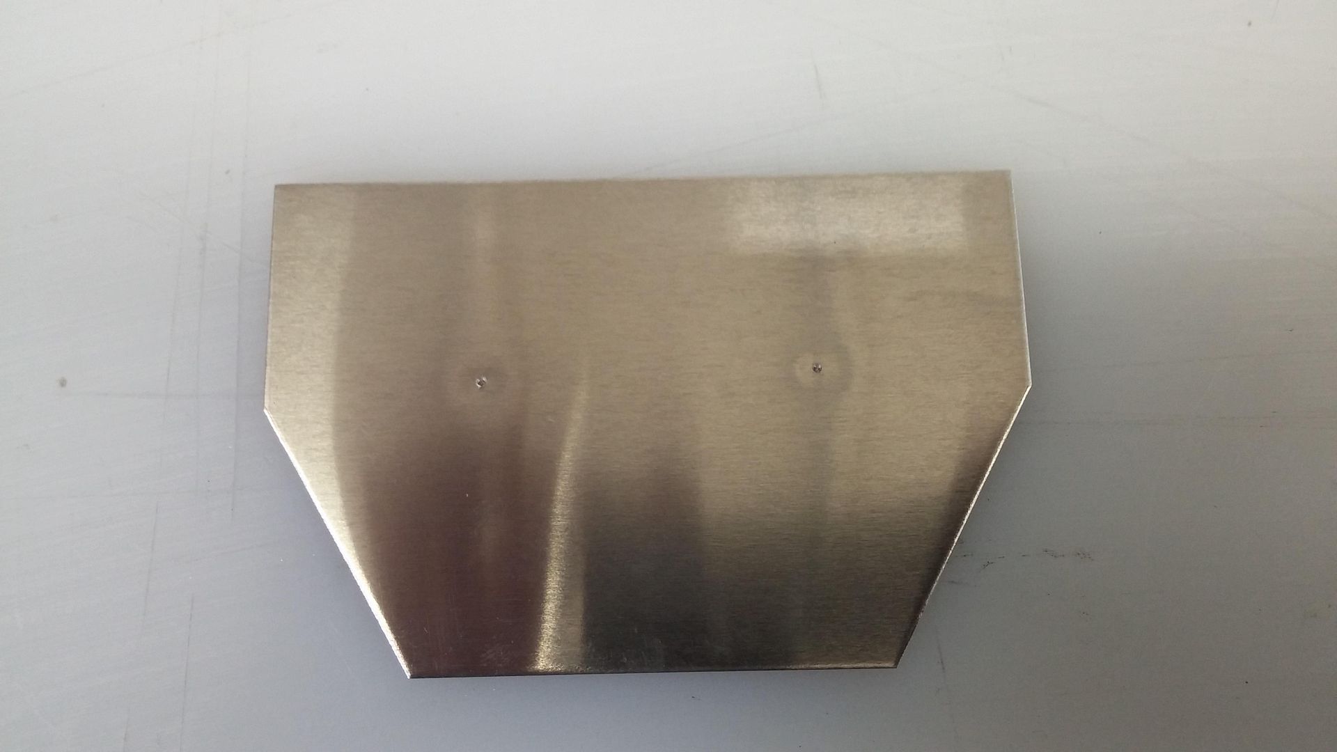
The blank trimmed.
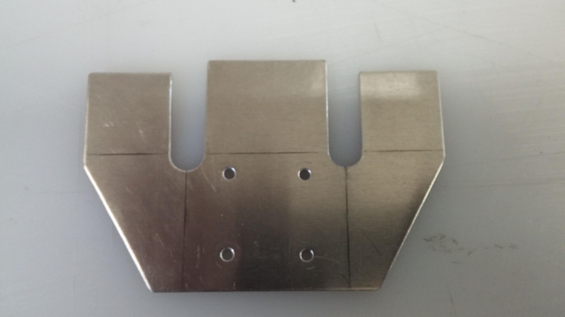
Then next with the tooling. Before I discovered the PVC, I used MDF and coupled this one with aluminum. The aluminum has the form and radii and the MDF is just for clamping. I also used brass pins to locate and hold the blank while forming.
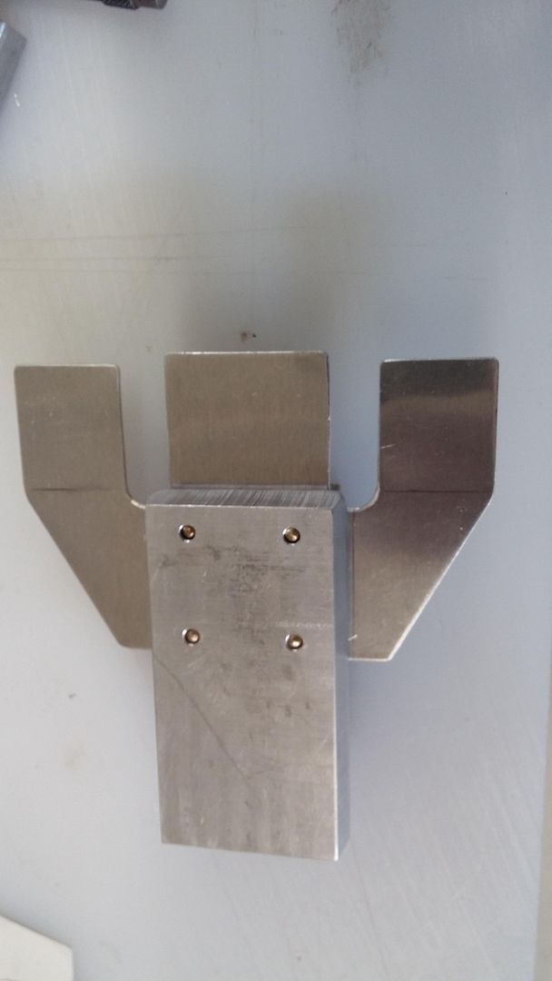
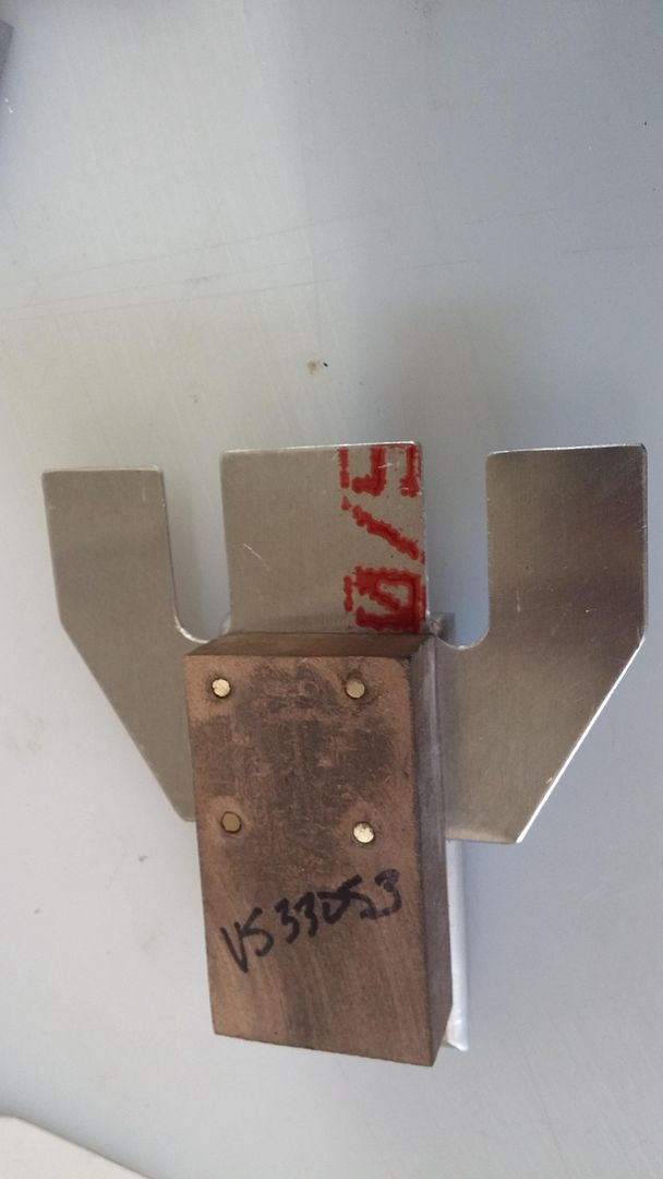
With the first fold made of the center piece, the sides are folded in and over the center piece.
In this picture you can see the second tool used. Looking through the fold radius cut outs, you can see an aluminum block. This has the radius necessary for the side folds but is cut down to allow the center fold to be recessed. The sides then fold over neatly.
The four holes are for riveting to the rib and there will be two holes in the "top" of the box to reinforce the oil cooler saddle.
Thanks for looking.