Hey WIX people, here's a riddle for you:
Q: What's big and blue, and has two engines and two props?
A: As of yesterday afternoon, Hot Stuff.
Yes, the big thaw is upon us. Two big snowstorms in two weeks, and frigid temperatures that would freeze the bits right off yourself, but Friday there began the warm-up, and it continued yesterday. A good day for working outside. Given that, and given that everything's been prepared and ready to go, let's hang that prop, shall we?
There's a very nice photo essay in the Diamond Lil thread on How to Remove a Hamilton Standard Hydromatic Prop--a very excellent source for refreshing one's memory on the sequence of events--but I never did find one for the reverse procedure. So I thought that this might be a good opportunity to do such an essay for Putting the Prop Back On. We've done this a number of times now, but hopefully, it will be long enough before we have to do it again, that we'll need a memory-refresher!
To start with, let's have a look at all the parts, laid out where we can have a good look at them ...

On the left is the dome, which contains the piston and drive gear. Because we (per the book) manually twisted the prop blades before removal, the drive gear is against the feathering stop (88 degrees). This gives us a datum for setting things up for reinstallation.
Under the dome is its rubber seal, which fits around the base, and the dome-to-hub shim. The shim, selected via an enormously complicated mathematical formula, matches the hub to the dome with optimum gear lash. You only need to do the math if you've changed components. We're just putting the original stuff back together, so we just use the same shim as before.
Inside the shim is the breather nut and its gasket. This item plugs the dome. For installation, a handle is screwed into its location in the dome.
Above the shim, from left to right: rear cone, which seats and centers the prop hub on the shaft; three-piece spider/shaft seal assembly; three-piece prop nut and split forward cone (secures the prop and centers it on the shaft, like the rear cone), and below it the prop-nut snap ring; and on the right, the distributor valve, its snap ring, and distributor valve gasket.
Let's hang a prop, then!
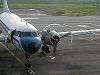
Having borrowed the forklift from our friendly and supportive FBO, Indy Aero, the first thing to do is to get the prop in the air with the forward side facing the forklift.

That, of course, is the exact opposite of what I just described. We're about to turn her around to face the right way. Everything in this process needs to be done nice and slow and carefully, 'cause props aren't free by any means, neither to buy nor to repair. So, no banging of the prop blades into anything, and no dropping it, for sure!

While these preparations are going on, we removed the barrier paper from the prop shaft and cleaned off all the oil with MEK. The shaft has to be clean and dry when you slip the rear cone into place--you can see it there, at the aft end of the shaft. Once the cone's there, then you lube up the shaft splines again, and the prop-nut threads. No oil under the cone, however; the book's very specific about that.
We've also already clocked the prop shaft so that the master spline (twice as big as the other spline teeth) is at the six o'clock position. This correlates to where the mating spline groove in the prop hub will be when we pick it up.

So, with everything ready, we lift up the prop and walk it slowly and carefully over to the plane, and get 'er lined up, and head up to the prop shaft. The prop shaft has fine threads on the end, just waiting to be boogered up, so once we're up there, we're moving things fractions of an inch at a time.

Now we can see the splines all lining up, and down just a little, and it starts on there. Once it starts to slide on, lower the forklift to slack the hoisting straps a tiny bit, and two people can easily wiggle it on down the shaft until it meets up with the rear cone.

Then it's remove the straps, and back the forklift out of there, and IndyJen can cease stressing over "omigawd, what if we drop the prop or bang it into the plane or ...", which is her way. Once it's on the shaft, it's not going anywhere, and now we can commence assembling the little parts from the first picture.

First thing to go in is the spider/shaft seal, a 3-piece garlock seal consisting of a washer, an outer phenolic u-channel, and an inner metal v-channel. They go in in that order, with the open side facing forward.
This, actually, is one of the places we've identified in the otherwise excellent PV-2 erection manual where there's a critical error. The PV-2 manual shows this seal installed with the open side aft, which won't give you much of a seal at all. Our several Hamilton Standard prop manuals all agree that this would be exactly backward. We go with the the prop manufacturer on this one.
Anyhow, you put the washer in place, down in there, and then carefully and gently use a couple tiny-blade screwdrivers to push the other two components, nested together, into place.
With the seal in place, it's time to put in the prop nut.

The prop nut and the two forward cone pieces fit together, and have to be installed together as a unit. Now, here's a tricky bit: when you finally put the dome on, at the end of this process, the blades have to be set to their feathered position (remember? the dome gear is pegged against the feathering stop?). Experience has taught us, however, that if the blades are feathered now, when we're trying to put in the nut, the gear geometry will just not let the cone get past, although you can get oh so close. Until this lesson was finally learned, oh, the frustration and profanity! But that was a long time ago. We know perfectly well to leave 'em in low pitch for now, so it starts right on there.

Screw it on by hand for a few turns to make sure all is well, and then you can get out the combination prop wrench, which is a gadgeteer's delight. For the prop nut, you use the big socket along with the funny-shaped combo wrench. Screw it all the way down until it seats, and then employ the carefully calibrated book torque to finish ("get a fat man and a three-foot bar ...")
No, really. The book torque for this is a 180-pound weight on the end of a three-foot bar. So we slip a bar of the appropriate length into the socket on the end of the wrench, select the appropriate mechanic, and ...

That's the basic torque. Then you get a big hammer.

See the holes in the prop shaft, and the corresponding slots in the prop nut? One hole and one slot must line up. You can only tighten to make this happen; never loosen. Using the same combo wrench/big bar combination as before, put pressure on the bar and rap smartly (on the bar, not on the wrench itself, which is a casting) until you're there.
Then you can install the prop-nut snap ring. This snap ring, along with safetying the nut, lets you take the prop off again--when you back off the prop nut, it will come up against this snap ring, and jack the hub off its seat.
Now it's time to install the distributor valve. First its gasket:

This item sits down in the bottom of the prop shaft cavity. Once it's in there, oil up the threads of the distributor valve, and carefully start it by hand. The threads are fine, and shallow, and easy to booger up. Boogering up the threads is not recommended. Be careful!

The book wants you to turn it in three or four turns before putting the wrench to work. We take this to be an "at least" value, and turn it in by hand until it bottoms. Then you get out the combination wrench again, and use the open-end place that corresponds to the flats on the valve:

Turn it down until it's ready for the actual torque, which is done similarly to the prop nut. This time, we want 100 pounds on a one-foot bar for the base torque.

Once that's accomplished, it's time to get out the hammer again. Remember the alignment we did with the prop shaft and prop nut? The distributor valve also has machine-in slots, one of which must align with the hole/slot we previously matched up. Once again, keep pressure on the bar while smartly rapping it with the hammer, until you have the lineup.
This is why:

See there, at about five o'clock? There's the lock ring, installed. It fits in an external groove in the prop nut, and goes through the previously aligned slot/hole/slot, making sure nothing moves from here on out.
Well, there we go. We're coming up on the end of the process now, and it's time to set the three blades to feathered position. There is a degree scale at the root of each blade. Hopefully you marked the position for each when you pulled the prop off way back when. The blades can be twisted by hand.

Put the shim in place over the pins in the hub.

Now put the rubber gasket on the base of the dome, and carefully lift it into position. Be careful not to damage the distributor valve when you're putting the heavy thing on there.

When you pulled the prop, long ago, you made match-marks on the dome and on the hub, so you'd know which way to align them. Get those marks close and then, per the book, rotate the dome counter-clockwise (never clockwise) as needed until the pins in the hub go into the mating holes in the base of the dome. Clunk! It's down on there. Now you can start threading the big ring-nut into the hub, securing the dome.
That ring-nut needs to thread all the way down by hand until no threads are exposed. If it doesn't, the dome gear is not meshed with all three blade gears. What to do at that point? Manipulate the blades until you can "feel" which one is high-sided. It may be all three, or two of them, or just one. Once you get 'em meshed, remove the dome, and check those blade-root scales again.
They must be all the same. Each tooth in the gear is eight degrees of blade travel. If you need to adjust one or two blades, do so, matching up the position of the teeth as best you can, and then try again with the dome installation.
Do this procedure approximately three thousand times, until finally, the ring nut screws all the way down quite easily, and no blades have to be messed with, and they all stay the same.
If you have a bodybuilder in your group, he (or she) is the one to elect for this remove-the-dome/install-the-dome/remove-the-dome-again process. It's a heavy item. Lots of reps. Great for the delts, or the lats, or whatever the heck muscle group. I'm not sure which muscle group, actually. I'll check with Scotty, who was doing this yesterday, and find out where he's hurting today. Feel the burn, Scotty!
Anyhow, once you've solved the gear mesh problem, you can get out the dome-nut wrench.

Once again it's fat-man torque, followed by the hammer to get the lock-screw hole in place. Install and safety that screw, and now you're almost done.
Remove the carrying handle from the dome, and in its place, install the breather nut. It's called a breather nut, because in some Ham-Std installations, there's an engine breather installed. Not in ours, however; that passage is just plugged. A washer and a special gasket make a three-piece installation, which screw into the same place where that handle was.

Tighten 'er down to a "that feels about right" strain, and once again, line up one of the holes in the nut with one of the slots in the dome, and install the lock ring.
And you're done!

Now we've got a weekend or two ahead of us, hooking up all the engine lines and cables. We have some new cockpit floorboards to install, and the seats, and then we'll be ready for test/set-up runs.
Before we run the engine, we'll make up our prop-blade-twisting tool (a couple big boards, some padding, a huge c-clamp) and put the blades back to flat pitch. You can twist 'em with your hands with the dome off, but once the dome's on, you need leverage galore.
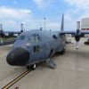
But in the meantime, she's looking more and more like an airplane that wants to fly, doesn't she?

Good times ahead!
Till next time,