Warbird Information Exchange

DISCLAIMER: The views expressed on this site are the responsibility of the poster and do not reflect the views of the management.
It is currently Wed May 07, 2025 5:49 pm

All times are UTC - 5 hours


Classic Wings Magazine WWII Naval Aviation Research Pacific Luftwaffe Resource Center
When Hollywood Ruled The Skies - Volumes 1 through 4 by Bruce Oriss


Post new topic Reply to topic  [ 208 posts ]  Go to page Previous  1, 2, 3, 4, 5, 6, 7, 8 ... 14  Next
Author Message
 Post subject:
PostPosted: Thu May 01, 2008 10:12 am 
Offline

Joined: Thu Jan 12, 2006 1:42 pm
Posts: 460
Location: Nevada
Larry;
Keep them coming I love it. Tanker #60 was the last air tanker I worked with in Reno before I moved south. Wally and Rich were flying it then. I think Rich went on to Aero Union and Wally to the BLM.
Scott..............


Top
 Profile  
 
 Post subject: A gazillion tks
PostPosted: Thu May 01, 2008 12:07 pm 
Offline
2000+ Post Club
2000+ Post Club
User avatar

Joined: Fri Apr 30, 2004 8:11 am
Posts: 2391
Location: Montreal, Quebec, Canada
A gazillion tks for the great tread and taking the time to answer all those questions.

May I ask what are those "bukheads ??" on the floor ?

They seem to be attached to the old seat railings.

Quote:
Image


Top
 Profile  
 
PostPosted: Thu May 01, 2008 4:16 pm 
Offline
User avatar

Joined: Mon Jul 17, 2006 6:59 pm
Posts: 837
Location: Redmond,Oregon
Michel,the box like structure is the "Floating Beam" for the retardant tank.It actually connects to the four main attachment brackets on the tank via torsion bars that are visible toward the center of the airplane and are painted zinc chromate green.I'll take some detailed pictures tomorrow.The purpose of this structure is to help to distribute the considerable weight of the retardant tank (1500 lbs.) and 3000 gallons of retardant (27,000 lbs.) across the front and rear wing spars.You can see that the crossways parts of the beam are located directly above the front and rear spars.

Tanker 66 was the "Mainliner Lincoln" with United Airlines between 1958-1964.Denver Ports of Call Flying Club operated the airplane from 1967-1975 when TBM Inc. bought it for conversion to a tanker.

Image

This is the Bendix Ignition Analyzer used by United.It gives the same information as the Sperry Analyzer favored by Eastern Airlines as mounted in Tanker 60.
Image

Image

Image

Image

Image

Image

Image

Image

Image

Image

Image

Image

Image

Image

Image

Image

These next two pictures show the main electrical junction box circuit breaker panel and the mount and sighting window for a periscopic sextant.
Image

Image

Image


Top
 Profile  
 
 Post subject:
PostPosted: Thu May 01, 2008 7:34 pm 
Offline

Joined: Sun Jan 14, 2007 5:11 pm
Posts: 53
Location: ohio
Larry, Your photos just keep getting better and better. What is the small wheel below and to the right of the mixture knobs? Do you carry a flight engineer in flight to moniter the ignition analizer and other engine instruments? Thanks Carl


Top
 Profile  
 
 Post subject:
PostPosted: Thu May 01, 2008 8:35 pm 
Offline
2000+ Post Club
2000+ Post Club
User avatar

Joined: Thu May 10, 2007 6:08 pm
Posts: 2595
Location: Mississippi
Larry, what are the odds of getting a shooter in the rumpleseat during one of yoru drops? Not me, mind, my days with a camera are done. But it would be pretty neat to get some pics of the fight from your perspective...

_________________
"I knew the jig was up when I saw the P-51D-20-NA Mustang blue-nosed bastards from Bodney, and by the way the blue was more of a royal blue than an indigo and the inner landing gear interiors were NOT green, over Berlin."


Top
 Profile  
 
PostPosted: Thu May 01, 2008 9:09 pm 
Offline
User avatar

Joined: Mon Jul 17, 2006 6:59 pm
Posts: 837
Location: Redmond,Oregon
Carl,
The small wheel by the mixture controls is for the aileron trim.The wheel above the glare shield is the rudder trim and the wheels outboard of the throttles on either side for the elevator trim.We use the elevator trim a lot during tanker operations,When you get below about 170 kts and make fairly tight turns,the elevators (not to mention the ailerons) get pretty heavy.It isn't unusual to crank in a full turn of nose up trim while entering a turn and having to turn it back coming out.Our speeds in the drop pattern are usually between 130-140 kts.

Incidentally,the wheel outboard and forward of the pilot's seat is for the nosewheel steering.I'll post some pictures of the interior aft of the cockpit from the other day plus some pictures that I took this morning with some cockpit items removed for access to route some antenna wires for the XM Radio that is part of the upgrade to our Garmin 430 GPS.That's supposed to give us images from broadcast realtime Doppler Radar.That should give us a "Poor Man's Weather Radar".The Aero Union P-3's had that service last year and raved about how well it worked.

Image

Image

This is the rear entrance door with the soundproofing removed.This was the main passenger entrance and had the flight attendant station and buffet on either side just inside the door.
Image

Image

Image

Image

Image

Image

Image

Image

Image

This is the aft overhead panel that contains the APU controls,among other things in the maintenance access position.
Image

This is the right hand engine instrument panel from the front and rear.As you can see,it's designed with quick disconnects for maintenance.
Image

Image

This shot is from the co-pilot's seat looking toward the removed pilot's seat area with electrical access panels open behind where the seat back should be.
Image


Top
 Profile  
 
 Post subject:
PostPosted: Fri May 02, 2008 1:42 pm 
Offline

Joined: Thu Jan 12, 2006 1:42 pm
Posts: 460
Location: Nevada
Larry;
Sure does look strange in the back of that DC-7 with no spare parts onboard! I can remember walking in the back of #60 and you could hardly get to anything with all of the stuff they carried back then, Do you guys still carry any parts on the ODF contracts, since your so close to the home maintenance base? Also is that a Can of Skydrol in the back with the pump hooked to it?
Scott.....


Top
 Profile  
 
PostPosted: Sun May 04, 2008 2:23 pm 
Offline
User avatar

Joined: Mon Jul 17, 2006 6:59 pm
Posts: 837
Location: Redmond,Oregon
First,I'll try to answer a few questions.Carl,we don't carry a flight engineer for tanker operations.The DC-6 and DC-7 didn't have a dedicated flight engineer position like those in Connies or C-97's.The enginieer in the Dougs just had a folding seat just aft of the throttle quadrant near the analyzer.In our operations,the pilot and co-pilot end up splitting the engineer duties with the c/p handling about 75% of them.The airlines also had waivers to fly non-revenue flights with just the pilot and co-pilot on these airplanes.Our major advantages are that we seldom fly in serious IFR conditions and we can make the airplane 27,000 lbs. lighter in a few seconds if necessary by jettisoning the retardant.That said,if we had a non-disposable load and flew in IFR conditions,a flight engineeer would be an absolute necessity.

Mudduboots,strangely enough considering how many windows thare are in the DC-7,it's not a good airplane to try to get good action pictures.The best picture that I've seen taken from my airplane is the one that I use as my avatar on WIX.That was taken by my co-pilot while orbiting the Million Fire in Colorado on an initial attack mission and trying to figure out what to do with one load of retardant.Usually,reflections are a major problem,but the light was just right in the case of this picture.I do have about 20 hours of video that I shot via a camcorder attached to the radio rack near the analyzer and shooting through the pilot's windshileld over my shoulder.I tried this in 1984-85.Someday,I'll have to transfer the best of that footage to DVD and post a few minutes of it.

Scott,we have to carry a certain amount of ballast in the back of the airplanes.With the retardant tank installed and empty and a low fuel load,without ballast,the airplane center of gravity is well forward of the allowable forward C.G. limit.Each airplane is placarded with a weight that needs to be carried just forward of the rear pressure bulkhead.On T62,I think that it works out to 617 lbs.We normally carry more weight distributed further forward,but calculated to cover the required ballast.We used to carry up to 3000 lbs. of spares,ladders,cleaning supplies and the like.For the Oregon contracts,we've cut that back to about 1500 lbs,but if you don't carry the required ballast,you can't flare the airplane when it's very light and it will touch down on the nosewheel,or worse.

I'll try posting a few prop system related pages from some manuals before posting the pictures of the retardant tank and floating beam.

Image

Image

Image

Image

Image

Image


Last edited by Larry Kraus on Thu May 08, 2008 12:26 am, edited 1 time in total.

Top
 Profile  
 
PostPosted: Mon May 05, 2008 9:32 pm 
Offline
User avatar

Joined: Mon Jul 17, 2006 6:59 pm
Posts: 837
Location: Redmond,Oregon
Scott asked if we carry a can of Skydrol hooked to a pump in the cabin.The answer is yes.It allows us to replenish fluid from inside the airplane.We can monitor the quantity in the reservoir with the guage near the fuel gauges.The access hatch to the hydraulic compartment is partially blocked by the retardant tank.You can get in there if you really have to,but it's a tight squeeze.The same goes for the small access door at the rear of the forward baggage compartment.

Image

Image

The hydraulic quantity guage is in the middle of the small instruments below the mag switches.

Image

Image

Here are some pictures of the floating beam that connects the reatardant tank to the airplane with four of the eight attachment bolts.There are two additional attachment bolts at the front of the tank and the other two are at the rear.

Image

Image

Image

Image

Image

Image


Top
 Profile  
 
 Post subject: Tks for the pics Larry
PostPosted: Mon May 05, 2008 10:34 pm 
Offline
2000+ Post Club
2000+ Post Club
User avatar

Joined: Fri Apr 30, 2004 8:11 am
Posts: 2391
Location: Montreal, Quebec, Canada
Tks for the pics Larry 8)

With the first pics from a distance, it looked like the attach points where using the seat railling system :roll:

Nice to see the size and of the holding components for the tank :))

Michel


Top
 Profile  
 
PostPosted: Tue May 06, 2008 2:30 am 
Offline
User avatar

Joined: Mon Jul 17, 2006 6:59 pm
Posts: 837
Location: Redmond,Oregon
In case anyone is interested,I took a few pictures of the controls in the cockpit that we use to drop the load of retardant.There is a Tank Arming Panel located above the co-pilot's quarter window where the pressurization control panel was originally located.An amber light come on when one of the eight compartment doors opens and remains on until the arming switch is cycled.This is the only indication that we have that a door has actually opened,other than the fact that the airplane gets lighter by about 3375 lbs. per compartmet as each holds 375 gl. of retardant.

Image

The pilot has a drop button on the control wheel that is normally guarded.It is shown on the outboard side of the wheel with the guard raised in the drop configuration in this picture.

Image

The pilot has three other controls to set to obtain an apporximate coverage level of retardant on the ground.The first is the intervelometer.It allows the selection of how many doors open at a time.Normally,we open single doors in trail.For heavier coverage,as in heavy timber,we might set up double doors instead of singles.This effectively doubles the quantity of retardant that reaches the ground in a given area.For very heavy coverage four doors can be opened at once.The last option is a salvo of all eight doors.This would only be used in case of a very high drop due to obstructions where the hope is that the load will stay together enough to be effective from above 300 ft.We seldom use this as it is a strain on the airplane.I believe that these intervelometers were designed for firing underwing rockets from attack aircraft.

Image

To allow approximate coverage levels,we have two additional selectors.One sets the interval between door openings in tenths of a second when the drop button is held down and the other sets the total number of doors to open.In this picture,they are set to .4 seconds and 8 doors.At 130 kts. and 150 ft. above the terrain,with the intervelometer set for single doors,I would get approximately a Coverage Level 6,or 6 gallons of retardant per 100 square feet on the ground.Setting .5 seconds would result in Coverage Level 5.Setting .6 would be Coverage Level 4.The tricky part is getting the airplane in the right place and direction,on speed and at the correct elevation and have an escape route figured out as well.Then I also need to avoid hitting any people or equipment on the ground,at least at higher coverage levels.I need to know which coverage level to use for the vegetation and terrain.We also need to try to keep the retardant out of any water sources as it can be poisonous to fish.Nothing to it.

Image

Image

Image


Top
 Profile  
 
 Post subject:
PostPosted: Tue May 06, 2008 9:53 am 
Offline

Joined: Thu Jan 12, 2006 1:42 pm
Posts: 460
Location: Nevada
Larry;
When did they go to Skydrol on the retardant tanks? I could have sworn they were Mil-5606 before. Thanks for of the cool pictures, I still hear a rumor of DC series airplane going on contract with Cal-Fire this year, and it is not turbine powered, per the RUMOR! You hear anything new on your end?
Scott..........


Top
 Profile  
 
 Post subject:
PostPosted: Tue May 06, 2008 1:50 pm 
Offline
User avatar

Joined: Thu Sep 29, 2005 10:19 am
Posts: 429
Location: new York
Larry,
I love looking at the detail shots. My dad was a Flight Engineer for Pan Am and flew on -6's and 7's before going onto jets. I was talking to him the other night while looking at these shots. He was getting all nostalgic and it was great to hear him talk about the old days. They had lots of problems with the R-3350, as well as the props. It took them awhile to figure out how to get any life out of them and the DC-7 literally gave my dad nightmares.


Top
 Profile  
 
 Post subject: retardant tank system
PostPosted: Tue May 06, 2008 2:34 pm 
Offline

Joined: Thu Jun 29, 2006 1:01 pm
Posts: 262
...
...good stuff Larry...

...Is that Aero Union tank system the same as was used on some of the DC-4s...except loaded lighter on the 4s ?...
...


Top
 Profile  
 
PostPosted: Tue May 06, 2008 5:22 pm 
Offline
User avatar

Joined: Mon Jul 17, 2006 6:59 pm
Posts: 837
Location: Redmond,Oregon
I'll try to answer a few more questions.For Sledge,yes these are Aero Union tanks that were originally designed with a capacity of 3000 gl. for the DC-6 and DC-7.When the DC-4's came along,they used the same basic tank design,but only filled it with 2000 gl. of retardant.The DC-4 tank and the P-3 version of the tank eliminated the floating beam inside the cabin.I'm not sure exactly how the center connecting bolts are attached in those applications.

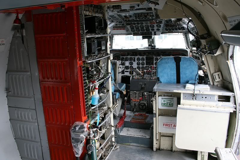
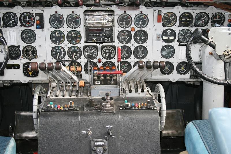
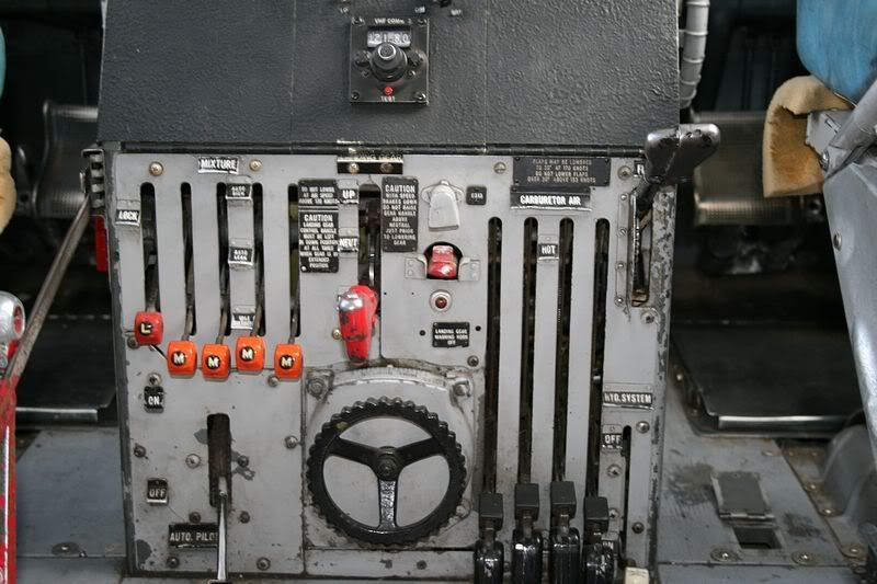
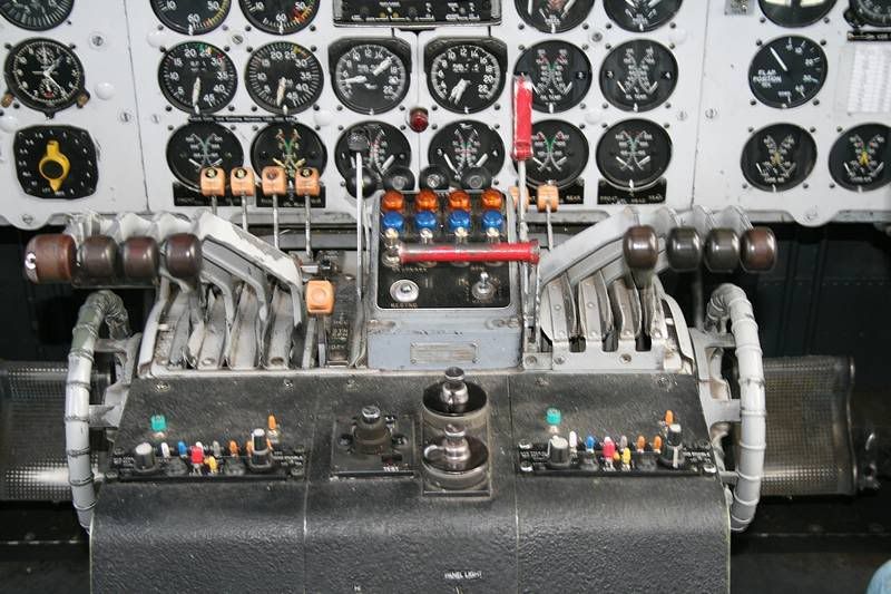
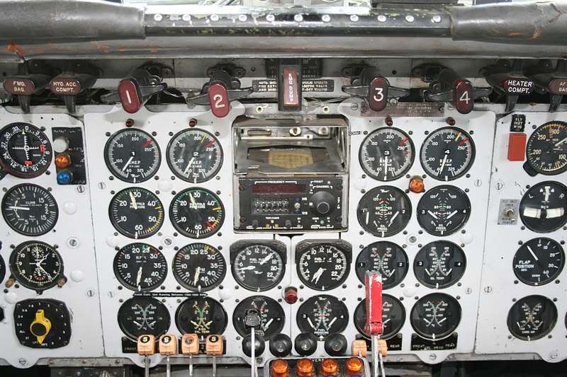
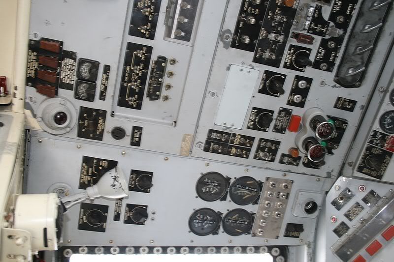
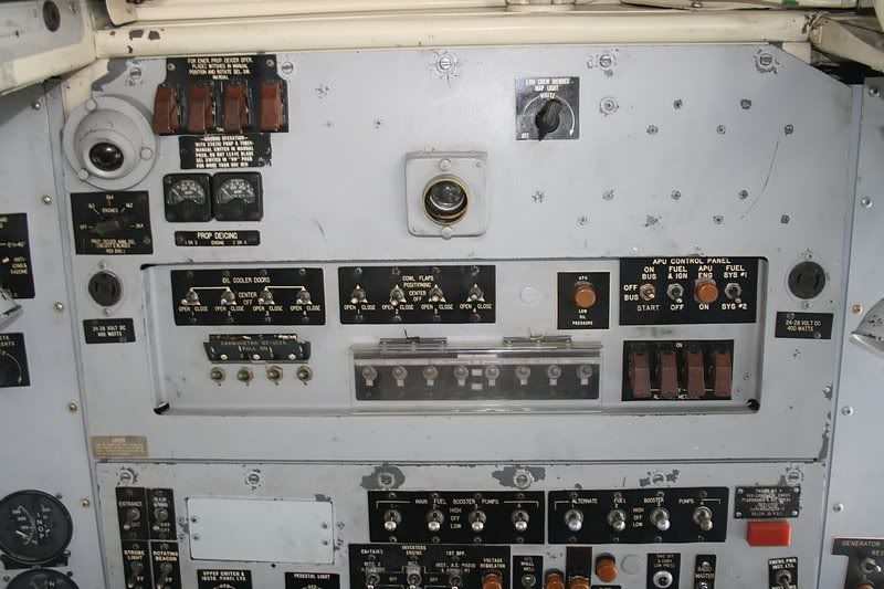
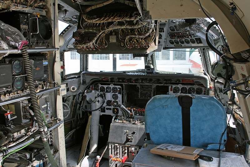
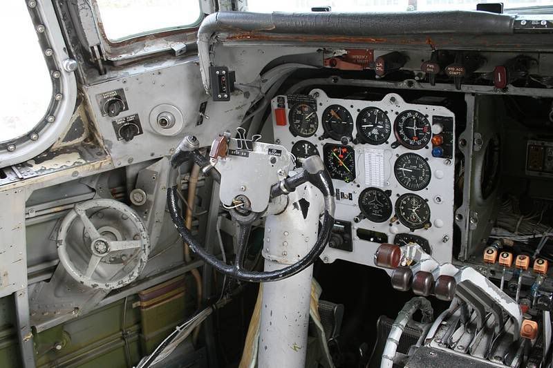
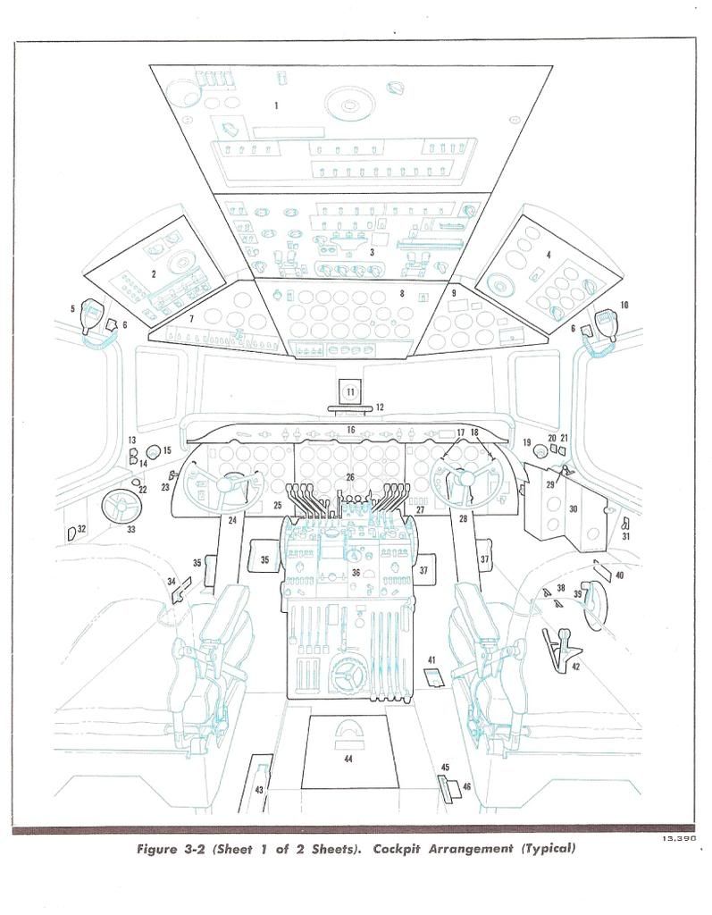
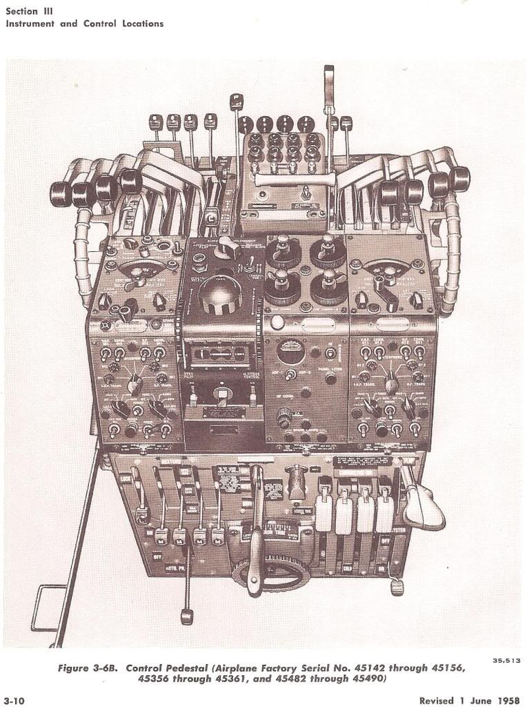
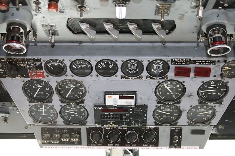
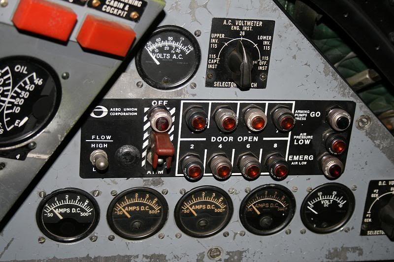
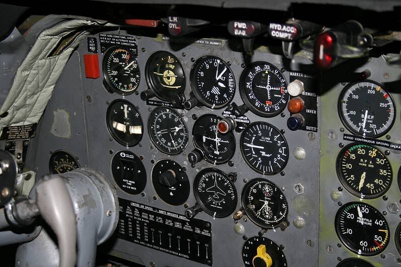
Originally,the tank operation was via a dedicated pneumatic system.This explains the labels for the three lights on the far right portion of the drop arming panel over the co-pilot's windshield which refer to air pressure.They now should read Hydraulic Pressure,but have never been changed.We had to modify the tanks to run via hydraulic pressure rather than air when the Forest Service required a "Low Flow" feature to drop at very low coverage levels to make long lines in grass and brush.Anything below about a coverage level 2 requied low flow.The solution was to hold the door partly open instead of fully open to restrict the retardant stream coming out of the tank.It also required diverter vanes between the doors to prevent the retardant from squirting sideways.It never worked very well and we very seldom used it and the whole low flow system has been disabled.

The P-3's and the later DC-4 tanks were redesigned as constant flow tanks with a computer operated variable single door instead of 8 doors.It is a far easier system from the pilot's standpoint because you just have to dial in a coverage level and push the drop button to start the retardant flow and let off of the button when you want it to stop.The computer varies the door opening width to compensate for head pressure as the load gets lighter and has a compensator for g loads.There is also a digital quantity readout for remaining retardant.We'd love to have our tanks modified to those standards,but at $250,000 per tank,it isn't likely to happen anytime soon.

Scott asked about Skydrol vs. 5606 hydraulic fluid in our airplanes.It all depends on which airline originally ordered the DC-7.Tanker 60 and Tanker 61 were ex-Eastern Airlines which used 5606 in their hydraulic systems as did our DC-6 Tanker 68,which was an ex-American Airlines airplane as was our Freighter/Test Stand.These airplanes used 5606.

United Airlines was,and still is,a big fan of Skydrol.Personally,I hate the stuff.But,Tankers 62 and 66 are ex-United Airlines as were DC-7 Tankers 67 and 69.All of these airplanes use Skydrol.It makes for logistics problems,but changing fluids isn't really an option as every seal and line in the airplane hydraulic system would have to be replaced to switch from Skydrol to 5606.

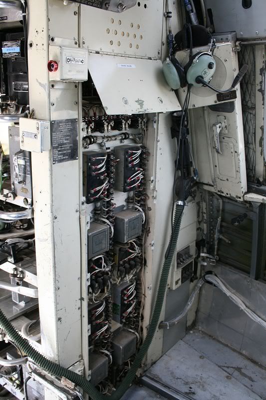
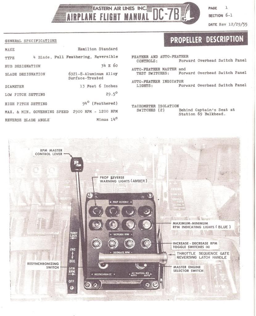
Skybolt,we still have some prop problems,but these are almost exclusively caused by broken or chafing electrical wires between the cockpit controls and the prop governor.There is a wire bundle that connects contacts via the prop slip ring and the governor that is the usual culprit.What most often happens is a breakdown in insulation on the wiring or an outright broken wire which will short to the conduit that contains the wire.The usual result will either be a fixed pitch prop (at whatever rpm it happens to be when the wire shorts) or the prop might change rpm in the opposite direction to what you had in mind when you try to adjust the rpm.Either one isn't desirable.

As to Engine problems.The worst of those are eliminated by our being forced to operate the engines at drastically reduced power settings compared to the airline operations due to the unavailabilty of 115/145 or even 100/130 avgas.Our climb power of 175 bmep and 2400 rpm is what the airlines used for cruise power,and that was in high blower and 10% lean while running cabin supercharger drives from the outboard engines.

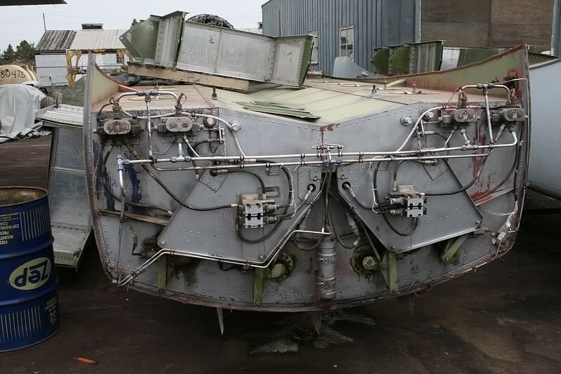
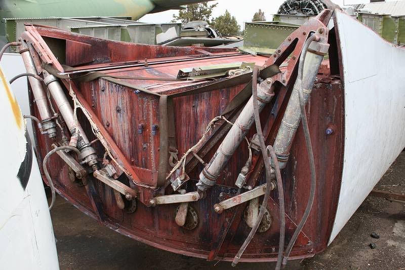
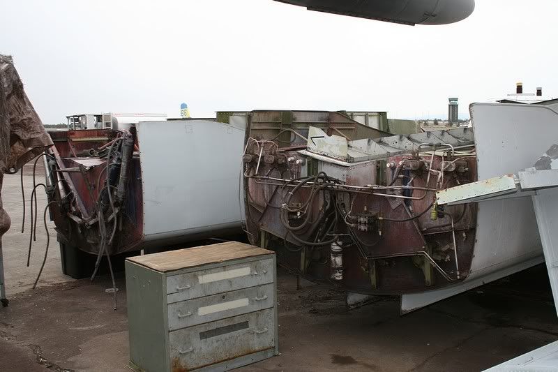
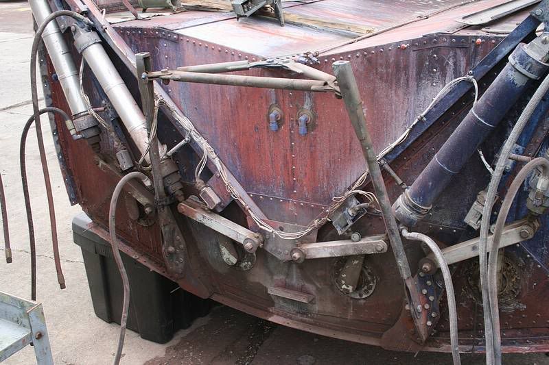
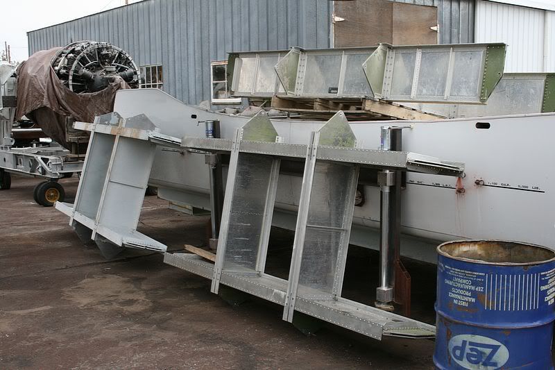
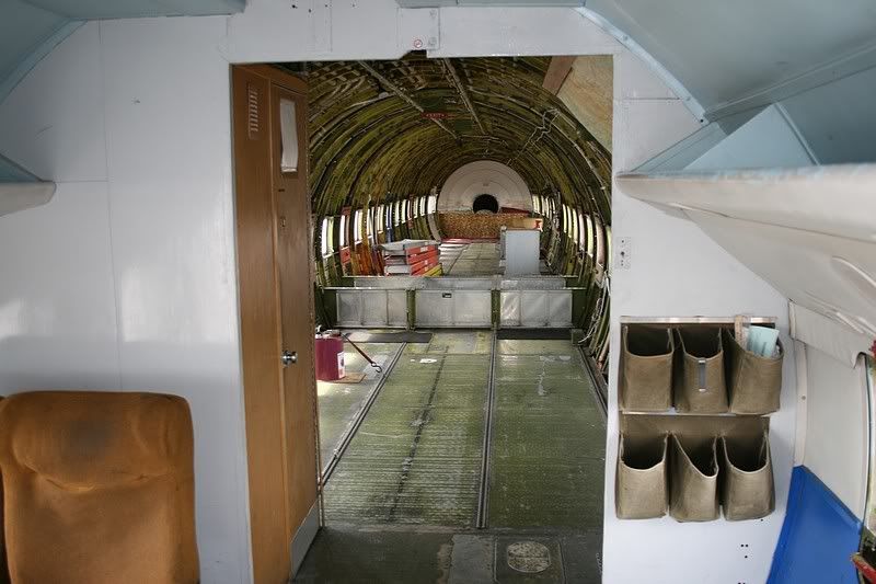
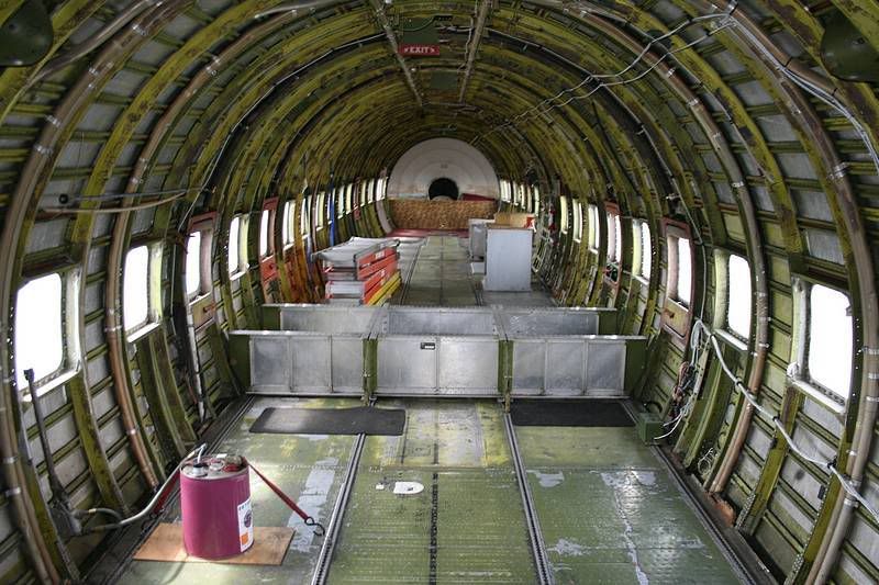
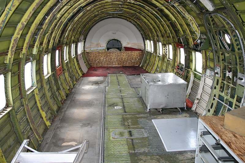
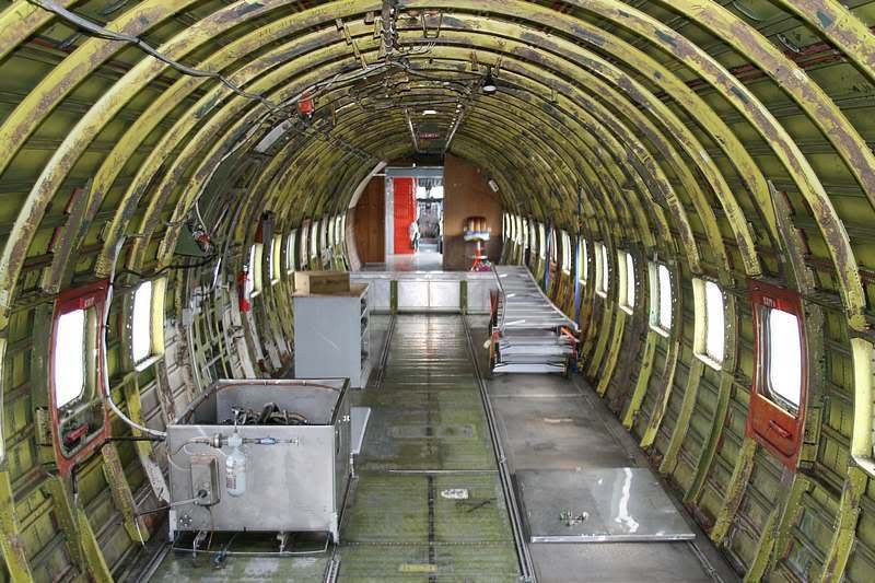
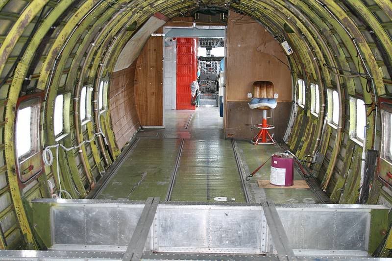
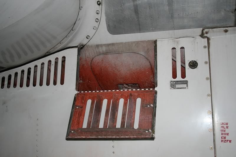
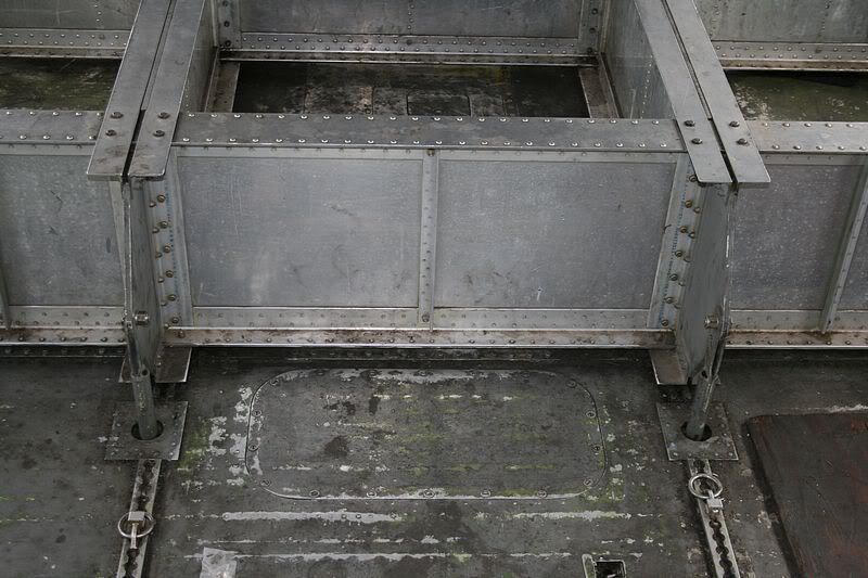
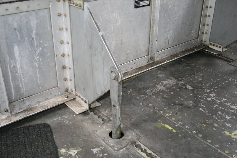
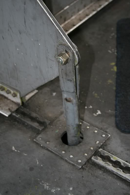
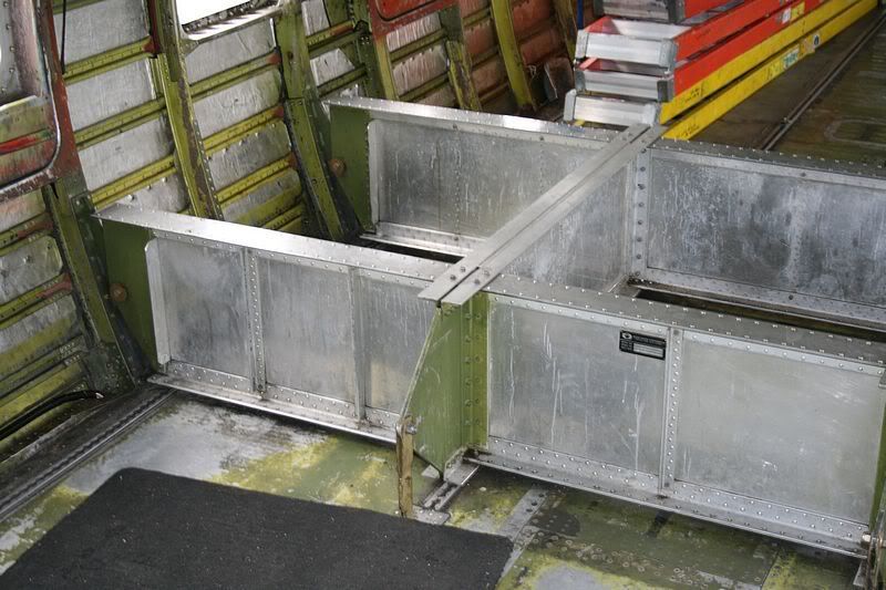
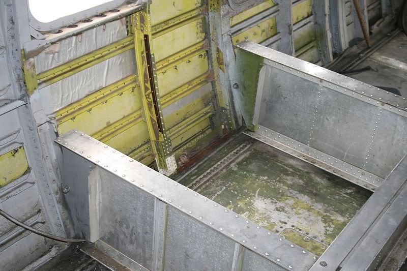
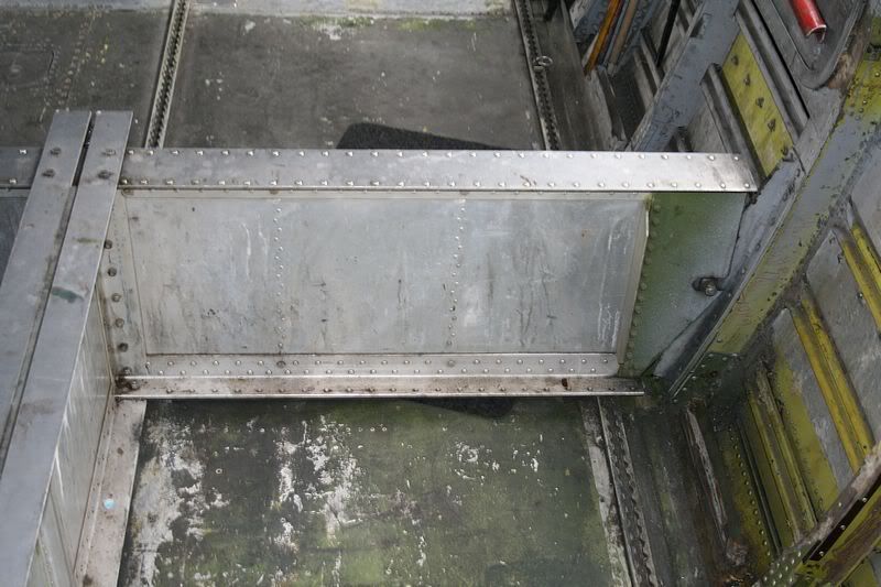
Here are a few pictures of some spare retardant tanks that were removed from tankers that were scrapped.Butler has three extra tanks that I know of.In the picture with two tanks,the closer one with the tool chest in front of it still has the diverter vanes for the low flow system on the bottom.

Image

Image

Image

Image

Image


Last edited by Larry Kraus on Tue May 06, 2008 11:58 pm, edited 2 times in total.

Top
 Profile  
 
Display posts from previous:  Sort by  
Post new topic Reply to topic  [ 208 posts ]  Go to page Previous  1, 2, 3, 4, 5, 6, 7, 8 ... 14  Next

All times are UTC - 5 hours


Who is online

Users browsing this forum: Google [Bot] and 337 guests


You cannot post new topics in this forum
You cannot reply to topics in this forum
You cannot edit your posts in this forum
You cannot delete your posts in this forum
You cannot post attachments in this forum

Search for:
Jump to:  
Powered by phpBB® Forum Software © phpBB Group