Fri Nov 16, 2007 11:51 am
The grip on the throttle is for a computing gun sight. This aircraft had a MK11D sight system which I beleive was a Fleet Air Arm mod.
This sight is similar to the K-14 sight used on the P-51D Mustang.
You would turn or twist the grip which would, through a fine cable, adjust the range mechanism of the gunsight. There was a circle of dots in the gunsight optics that you would adjust to the wingspan of the aircraft that you were shooting at.
If you knew that you were shooting at say an Oscar with a wingspan of 37 feet you would set this figure into the sight by adjusting a lever on the front face. Then when you kept the ring of dots on the wingspan, or your estimate of the wingspan, by twisting the throttle handle. This would tell the computing sight how far out the fighter was (range). The computer would adjust the floating reticule, or pipper as it was also called, to compensate for the range and other factors. The sight also had a gyro to sence acceleration for lead. It evidentally was a good system as different versions of it were used well into the jet era.
Fri Nov 16, 2007 12:02 pm
The only thing to add to this discussion is to sort through the differences between the different models and mfgs to be specific to the model you wish to present. Between the British (Notice the large handle on the throttle, similar to a Harvard), Goodyear (different switch locations as with the gear handle) and Vought models there will be differences. Even within the same mfg you will have changes introduced during production as technolgy and needs changed.
A pilots handbook should give the use of the switches and label them as such.
The flare box might be for storing starter shells. I don't know what was on the Britsh Corsairs but many early Navy fighters used a shotgun starter. There was a breech in the cockpit. A shell was loaded and fired after the engine was primed. The gasses would travel through a line to the starter which would spin up a flywheel that was then engaged. Just hope that everything was properly set for a start otherwise reset and do it again.
Oh yea, hope that you don't get an induction fire during the start. The best way to deal with that is to blow it out when the engine starts. With an electric starter you can do that. Not so easy with the shotgun starter.
When I took care of the FG-1D that Shipley had you could hear a certain poof sound when you caught on fire. Usually you heard it just before the engine would start. The fire extingusher guy made weekly runs by our hangar for a while until I had the carb overhauled. It is an updraft carb so gravity works against you for a bit of fuel spilling out. The real great design is that the exhaust is real close to where it drips the fuel.
Rich
Fri Nov 16, 2007 12:26 pm
Taigh Ramey wrote:Thanks for the correction. I thought the FAAM Corsair was a D.
Glad I could help.
Taigh Ramey wrote:I believe that good Corsair cockpit shots are hard to find because it is not easy to stand next to the cockpit to take a picture. You are either hanging on to the cockpit rail or you need a ladder or stand since the wing is so far forward of the cockpit. Or you can stand on the seat like the guy above.
Agreed.
Taigh Ramey wrote:I found very few good shots at National Archives of the interior. I have seen lots of good exterior shots but few inside.
Vought has given me written permission to copy their data that is at the National Archives, but it's a long, slow, and expensive process. I bought the index of their Corsair material almost 3 weeks ago and have not seen anything yet.
Taigh Ramey wrote:I have other shots looking down what are you looking for specifically?
I should have mentioned this initially, sorry.
I'm building a 1/6 scale (82") RC version of the 1A flown by Lt. JG Jim Streig who flew #3 for the Jolly Rogers (VF-17). It will have retractable landing gear, folding wings, the canopy will open/close, just to name a few of the things I will be adding.
I want the cockpit to be as close to accurate as I can make it. At 1/6 scale the labels will be readable. I'm not going to add plumbing, wires, etc but if I had pictures of the floor I could cut and paste them together, print it out on decal paper, and lay that one the floor to give it the look of a real floor. The hydraulic pump, tanks, leg supports, etc will be placed on top of the floor so it will have a 3D effect.
So, if you have any pictures of the floor at all they will be gratefully appreciated.
Taigh Ramey wrote:I think the two clips on the left side were for thermite grenades but I haven't confirmed this. Army aircraft carried these grenades to destroy the aircraft in case of capture.
It looks like the aft clip was factory and that maybe the forward one was added. I would have expected one thermite grenade not two. If you have any other information on this I would like to learn more about thermite grenades in Navy aircraft.
This is news to me. What clips on the left are you referring to? I don't see them in the 1st pictures.
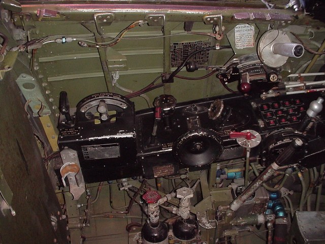
Taigh Ramey wrote:There are a bunch of flare gun cartridge clips on the right side next to a flare gun pouch. I believe these were added by the Royal Navy but this is also an unsubstantiated guess on my part as I have no supporting documentation. There is what appears to be a factory flare cartridge case mounted forward under the right side of the instrument panel.
It just looks like the clips in this photo are rather crudely installed.
Here is what I think is the factory flare cartridge case which is just to the left of the stick grip. It appears that the lid is missing.
I'm no expert but I would agree with you on these clips.
Thanks very much for your help.
Richard
Fri Nov 16, 2007 2:20 pm
The spring clips that RMAllnutt was asking about are on the left side of the cockpit just forward of the armor plate. In this photo they are the two staggered clips on the left side of the photo.
It could be that both were added by the Royal Navy. The one on the left has that classic British interior green color. The other looks more factory but it is purely a guess. I do not have my FG manuals nearby to check to see if they had the grenades and clips.
I believe that the clips and the box on the right are for the flare gun cartridges as they look like they are for the 37mm size rounds. I thought the cartridge starter rounds were smaller. Anyone know the size of the cartridge starter shell?
Fri Nov 16, 2007 5:07 pm
Taigh Ramey wrote:Please tell Chad that Taigh says hello.
Will do- sent you an email as well.
I was noticing that the throttle grip looks the same as in a Sea Fury or Spitfire/Seafire. Interesting...
Ashley
Tue Nov 27, 2007 9:14 am
I will be visiting the Tri-state Warbird Museum in Cincinnati this weekend. Their website is http://tri-statewarbirdmuseum.org so if you see anything you would like for me to get pictures of let me know.
I will be getting pictures of the FG-1D they are restoring. I can use the pictures for my model. They have the seat and much of the hardware out of the way so the shots should be good.
I will be getting pictures of the FG-1D they are restoring. I can use the pictures for my model. They have the seat and much of the hardware out of the way so the shots should be good.