Hello All,
After the amazing amount of feedback and interest in the P-35 project I am sorry for the long delay in replying. Due to a temporary assignment out of town for my day job (A&P) I have really been out of circulation. As a result not much time was available to work on anything Seversky related.
To answer the basic questions the following are VCS objectives for the "VCS35" replica:
1. The "VCS35" aircraft is to be powered by a R-1830-92 P&W powerplant as fitted to the C-47/DC-3. The aircraft was orginally powered by (P-35) R-1830-9 and (P-35A) R-1830-45 that are nonexistant. For mock up and preliminary fitting FWF (firewall forward) as many C-47 parts will be used as possible (engine mount, accessosry cowling ect). To this end a core R-1830-92 rear accessory case and C-47 upper accessory cowling have been found and purchased. I am still trying to find a C-47 engine mount and dishpan (exhaust shroud).
2. The "VCS35" aircraft will have the Hamiliton Standard 3E50 counterweight propeller replaced with the HS 23E50 hydromatic propeller. As (again) the counterweight propeller is nonexistant and the 23E50 is very available. A nonfeathering 23E50 hub similar to what is fitted to the new build Yak-3 was purchased. I am still looking for a set of three blades.
3. The "VCS35" will be a full scale, all aluminum flyable replica of the Seversky/Republic P-35A. To enable remanufacture, an effort is under way to completely "Loft" the aircraft with specialized software. This will define the true and accurate airframe design from which all parts will be built around. All jigs, fixtures will be designed and parts will be redrawn with 3D CAD software and checked for fit and structural integrity. This process mirrors the development and engineering of current aircraft design. The flaws and difficulties encountered (see Airbus A380 and Boeing 787) with this approach and been carefully compared with the amazing potential of what can be accomplished with state of the art manufacuring methods (CAM , rapid prototyping ect.)
4. To validate the design and manufacturing process, several small "proof of concept" projects were undertaken. The results were what I posted in the pictures. A completely new P-35A instrument panel was drawn in 2D CAD, and then cut out by a CNC mill. The firewall was also redrawn in 2D CAD and the shape was cut out of MDF with a gantry CNC router. Finally the seat, a modfied T-6/P-51 seat, was used as a pattern to model in 3D Cad and all sheetmetal parts are being modeled presently.
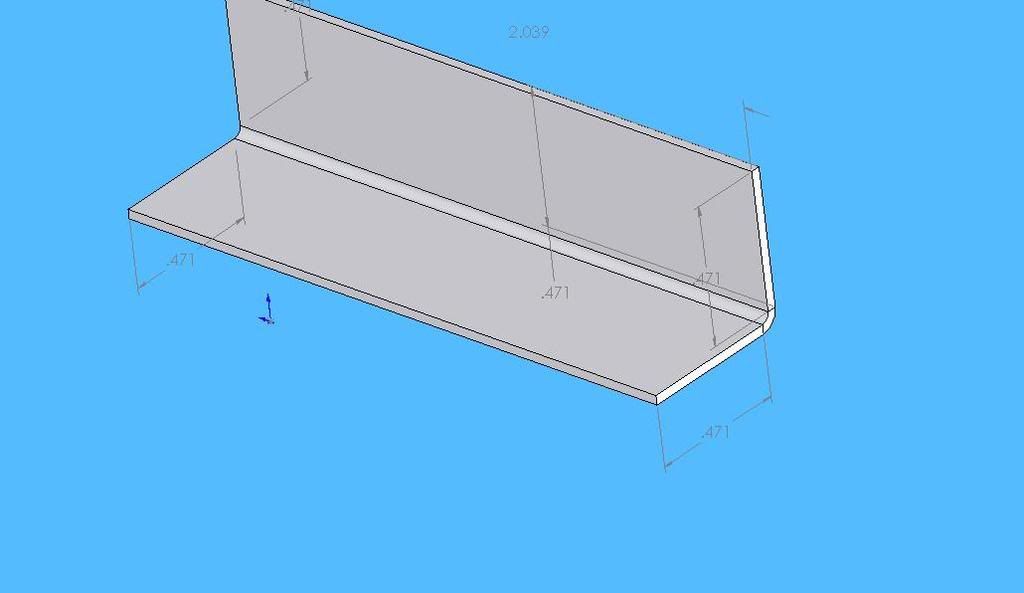
The following is an example of a modeled 3D CAD simple seat bracket:
The hope to soon began construction on the fuselage jig:
I will post more images of parts and progress. If any one should want more information please PM me.