Simple Rib Building
Sat Feb 23, 2008 10:11 pm
Here are some examples of an early project undertaken to prove "paper to part". I have learned alot since then, these were scaled down rib blanks.
First a design was created in a 2D CAD program:

Then form blocks were created out of (1) MDF and (2) Oak. I manually routed these my hand and wanted to see how both materials worked. Then aluminum "blanks" were fabricated using standard fabrication methods:

The blanks were them set on the form blocks:

And pressed into shape with a hydraulic press and rubber mat:

Some "hand finishing" with a mallet was necessary to get the right shape. The final result:

I will post more projects as I work on them. Basically I want to combine new manufacturing methods and design (CAD and CNC) with conventional aircraft production techniques.

First a design was created in a 2D CAD program:
Then form blocks were created out of (1) MDF and (2) Oak. I manually routed these my hand and wanted to see how both materials worked. Then aluminum "blanks" were fabricated using standard fabrication methods:
The blanks were them set on the form blocks:
And pressed into shape with a hydraulic press and rubber mat:
Some "hand finishing" with a mallet was necessary to get the right shape. The final result:
I will post more projects as I work on them. Basically I want to combine new manufacturing methods and design (CAD and CNC) with conventional aircraft production techniques.
Sat Feb 23, 2008 11:30 pm
Nice work, What are these for? Just proof of process? Also what CAD program are you using?
Shay
_____________
Semper Fortis
Shay
_____________
Semper Fortis
Sun Feb 24, 2008 9:35 am
The original rib was done in 2D Autocad 2000 based on a scaled down P-51 flap rib. I have since moved on to use 3D Solidworks which offers a sheet metal package that allows designs to be "unfolded" on the screen. It also will calculate bend allowance ect, and will enable me to plot a ready to manufacture pattern.
This was just an exercise (actually done in 2003) to validate the technology I was looking into. I was trained an A&P mechanic, so I was aware of the process of sheet metal fabrication. However design and CAD work were all new to me. This was a start to see if I really could build parts from CAD prints taken from microfiche aircraft blueprints.
I have learned a lot since then and I have been trying to use it to redesign and fabricate parts for my P-35 project.
Sun Feb 24, 2008 12:29 pm
For making ribs that aren't so straight sided you may have to clamp a plate on top to keep the radius tight.
Sun Feb 24, 2008 1:03 pm
I used to use aluminum form blocks with aluminum clamp blocks to hold the piece tight. The clamp block was always smaller, usually by the material thickness per side. Then formed with a rawhide mallet.
Great for reproducing lots of pieces.
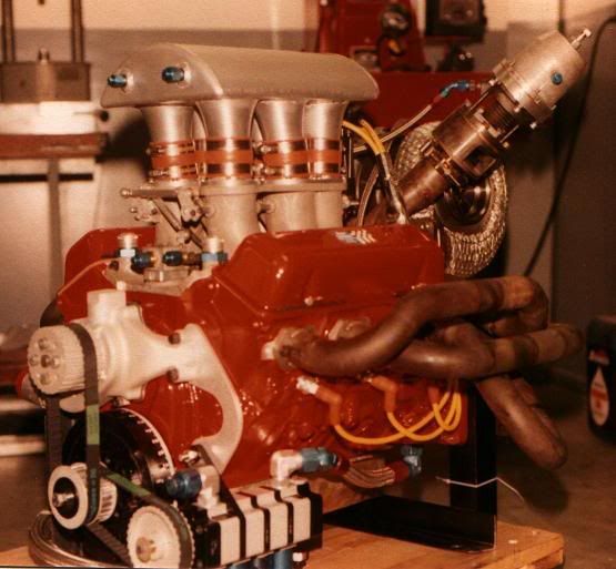
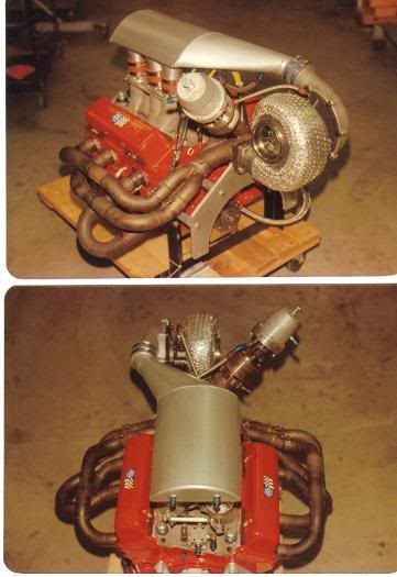
A great secret for creating the radii on the form blocks (or any other aluminum piece I wanted a radius on) is a normal router with a carbide cutter. WD40 was a great lube. Here are a couple shots of manifolds I made using the form blocks for the ends with the dash six fittings. My clamp bolts went through the holes where I welded the fittings
Making V-6 intakes from V-8 manifolds was a gas as well.
Great for reproducing lots of pieces.
A great secret for creating the radii on the form blocks (or any other aluminum piece I wanted a radius on) is a normal router with a carbide cutter. WD40 was a great lube. Here are a couple shots of manifolds I made using the form blocks for the ends with the dash six fittings. My clamp bolts went through the holes where I welded the fittings
Making V-6 intakes from V-8 manifolds was a gas as well.
Sun Feb 24, 2008 3:12 pm
Cad is great for printing but 3D is the way to go to design the parts.For large parts Waterjet for the aluminium and lazer for your former blocks as paper will creep and you end up with errors in your shape.All our Spit frames are hand beaten around wooden formers.Just have to shrink,stretch the flange afterwards to keep the frames straight..For more hands on stuff check out our webpage at the bottom of this post..

this is the Frame 9 aft centre channel on the Spitfire.
this is the Frame 9 aft centre channel on the Spitfire.