Page 1 of 1
Oddball streamline tubing needed (who can make some?)
Posted: Mon Sep 29, 2014 9:18 pm
by Baldeagle
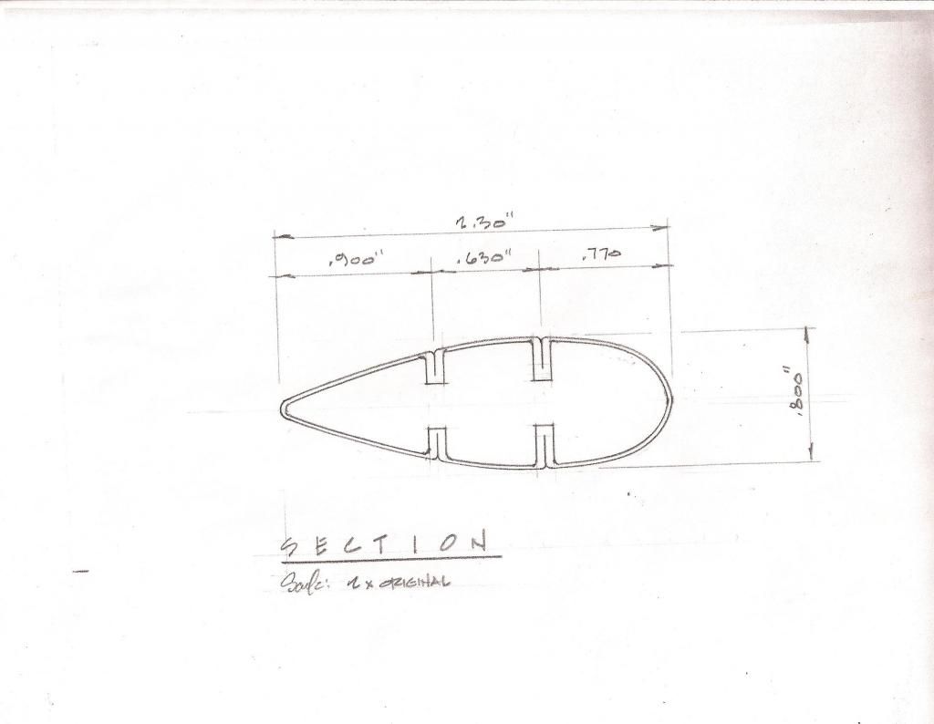
A friend and I recently bought an original 1934 Pietenpol project, but it looks like the wing struts may be unairworthy. They are a very unusual cross section, and we wondered if it might be possible to have some new ones formed. They have built in stiffening ridges, eliminating the need for jury struts. Here is a drawing of the cross section

I believe that they were first formed in a flat section with the ridges folded in, and then that was formed into the streamline section, and the trailing edge welded. You can feel the weld beads on the trailing edge of the original tubing. I think the thickness is .049", and I'm sure it's mild steel. Anybody have ideas on who might be able to make some 8 foot sections of this stuff?
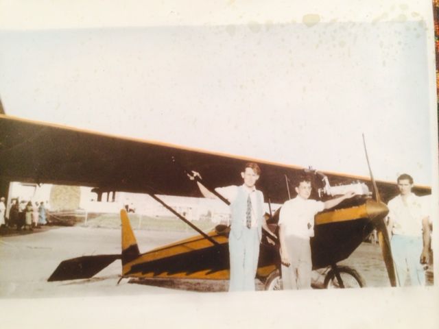
Here is a (hand tinted colorized) photo of the airplane in 1934

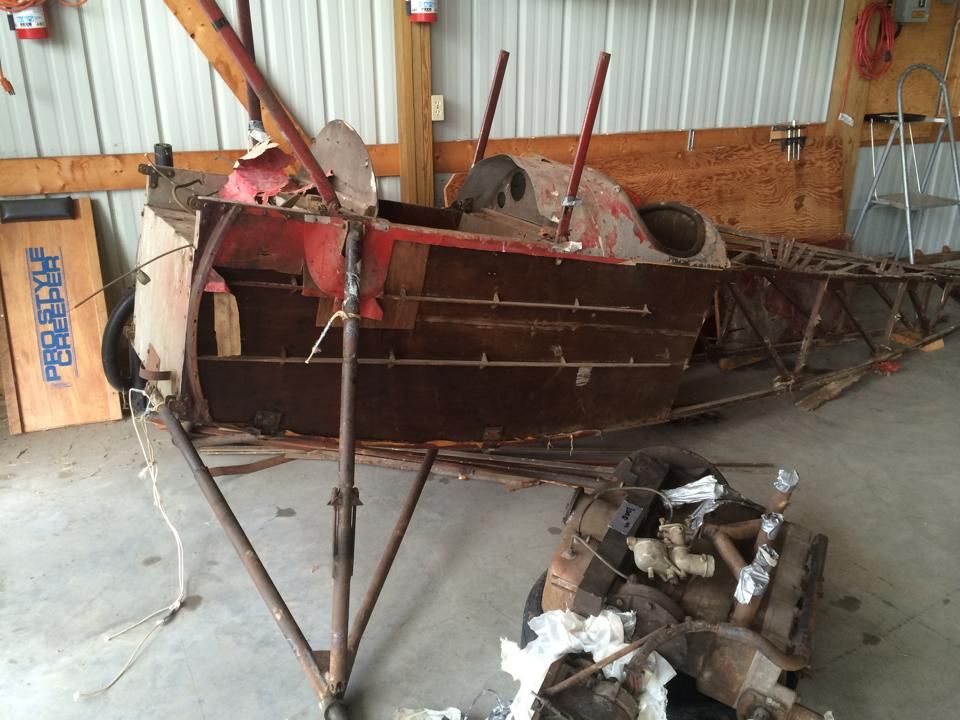
And as it looks today

The wing is gone, but we've already purchased one, and most of the rest of the original stuff looks useable.
-
Re: Oddball streamline tubing needed (who can make some?)
Posted: Tue Sep 30, 2014 1:37 pm
by Cvairwerks
That's a doosey to have formed. I would bet that it was folded hot and in stages. You could do it with a roll former, but just the dies would cost way more than the project and the rest of the budget. I'd bite the bullet and go with standard struts and jury struts. John M. or Franzkait over on the other site might have other ideas. To do enough material, I wouldn't be suprized if it was approaching $10K.
Something else I just thought of....could it be that those are 5 pieces welded together?
Re: Oddball streamline tubing needed (who can make some?)
Posted: Fri Oct 03, 2014 7:28 pm
by ZRX61
Possibly Airframe Assemblys in the UK?
Re: Oddball streamline tubing needed (who can make some?)
Posted: Mon Oct 06, 2014 1:26 pm
by bdk
You could get a regular piece of stramline tubing and put a broomstick inside to stiffen it. I think this is common Steve Wittman homebuilt practice.
Let me ask you this though, are you planning to do outside loops? Those stiffeners are only effective in keeping those struts from buckling. In normal flight, the struts are only in tension.
Re: Oddball streamline tubing needed (who can make some?)
Posted: Wed Oct 22, 2014 6:35 pm
by Tiger Tim
I suspect the jury struts would be well worth it. If all you had to do is run some kind of stiffener down the inside of a strut I'm sure Piper, Taylor, Aeronca et. all would have do e it that way.
Love the spinner and paint in the pic you posted. Your Piet thought it was a Heath!
-Tim
Re: Oddball streamline tubing needed (who can make some?)
Posted: Tue Mar 31, 2015 5:37 am
by powerandpassion
This tube seems straightforward to make using a brake press with an 8 foot spread, but would be fussy, but then the aircraft looks fussy, a sugar !
I can see three sections : nose, tail and channel (X 2, same section turned 180 degrees).
I would CAD up the three sections then laser cut biscuits of the sections out of any second grade steel plate to hand.
NB - (1) set laser to cut width/gauge of finished strip of strut. (2) set each biscuit within a square shape so you end up with a male former and a female former that nestle in each other, less width of laser cut.
Each biscuit would have two holes through it's centre. Depending on the thickness of the sheet I would lay up 100- 500 biscuits, put a threaded rod through them via the two holes and clamp the arrangement up. This would result in a crude press brake male and female former. If you know your press brake, CAD in the clamping arrangement into the biscuit. Do your CAD biscuit a pinch of salt less than finished dimension, smear your tooling work faces with a film of epoxy filler and sand smooth. I assume you are pressing SAE 4130, not 2024 aluminium.
Each biscuit would not have the return legs on your finished part. To achieve this turn your female tooling upside down, put your first presswork in then put in a new male biscuit former that sits down lower and allows you to start bending the legs over by hand, then finish with a square die to fold legs down fully. Remove arrangement from press and rattle captured male die out the end.
Nose, tail and two channels can them be butted together using a few biscuits as jig clamps, allowing you to run a weld join in the valleys formed by the kissing legs.... This advice may be entirely unhelpful, but I betchya you have never been advised to weld kissing legs before !
A streamline section with four internal stiffeners is probably the strongest section I have seen in such an application, albeit heaviest. I figure they gauged down in comparison to a cold drawn tube section. It actually is amenable to once off production in a small workshop, a very interesting design, the more that I think about it the more that I like it.
There is an analogy in Boulton-Paul tube formed from strip in the 1920's, used in Airship R101, and the fuselage longerons of Bristol Bulldogs. These use mechanical folds/seams rather than welding and non welding Nickel Chrome alloy steel. It would be worthwhile getting the chemistry of your remnant streamline to confirm that 4130 would be suitable and making extra sections to destructively test, as they seem such a fundamental part of the structural design.
It would be interesting to etch the original weld join to see if there was any heat treatment post welding on the original part. I suspect there is a lot of redundancy in the design, but its worth checking.


