Was finally able to do some tinkering to Another Solution this weekend. My high-speed, low-drag camera's display screen is messed up, so taking pictures where the details of what I've been doing is kind of difficult. So, I didn't take progress pictures...only photos of the completed fabrication.

Several things have taken place. First, the progress of the airplane looks further behind, as I've removed the wings and landing gear.

A.J. Smith, maker of the SnoShoo racer, is going to make me some nice carbon fiber wheel pants and such, so I'm just shipping my gear directly up to him to facilitate a speedy fabrication of the parts. So, in the mean time, while the main gear was getting worked on, I decided I needed to get my tail gear assembly fabricated and installed. Although I initially didn't have a clue as to what configuration I was going to go with this, I eventually worked it out and it ended up being a fun project. The end result has made me pretty happy.
You see, many of the faster Formula One racers simply have a fixed, non-steerable, tailwheel (usually nothing more than a roller blade wheel) bolted directly to the fuselage. This is great for keeping the drag down, but makes it tough to taxi around. I know that some of the guys simply skid the tailwheel sideways when leaving the runway after a race and rely heavily on their tow vehicle to get them back and forth to the pits. Well, I don't plan on flying this airplane only one time a year...I plan on flying it quite a bit. So, I need something that'll be low drag (and light) for racing, yet capable of allowing me to taxi around without skidding the tailwheel around (which is also a lot of unwanted stress on the lower longerons of the fuselage).
One thing (out of many) that is cool about this tail section that was originally on the Wagner Solution, is that it was made to "hide" a tailwheel. At the time, that airplane just had a tailwheel fixed in one place as mentioned before (and at one time a metal tail skid

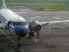
). This can barely be seen in some of the early pictures of the airplane that Neal Nurmi has posted on this thread. So in this photo, you can see the cutout for the tailwheel, in the bottom of the vertical fin for the airplane.....

In order to fabricate the complete tailwheel assembly for Another Solution, I utilized an existing tailwheel spring that came with this project, and an old tailwheel assembly that I'd obtained from a Cassutt Racer I'd tinkered with many years ago. The wheel and the hardware pictured in this update are temporary only. The wheel will be replaced with a roller blade wheel (they can take a huge amount of abuse and tend to work quite well in this situation).
I nearly made this a steerable tailwheel, by linking it directly to the rudder. However, I got to thinking that it would defeat the purpose of "hiding" the tailwheel if I put a linkage rod out in the breeze. So, I decided to go with a "lock & unlock" style of tailwheel. These aren't quite as desirable (in my opinion), but do work fairly well. I used to fly a Pitts Special that had the famous Haigh Tailwheel installed and had mixed feelings about it. While it was excellent in helping keep the airplane going straight down the runway, it was cumbersome to taxi with, as in that particular installation, I had to keep reaching over to a cable to unlock the tailwheel each time I wanted to turn. What I wanted here was something like the P-51 Mustangs (and many AT-6's) have. When it is needed to unlock the tailwheel on a Mustang, you simply push the elevator forward. This releases a pin on the tailwheel and allows it to caster freely. Now, that is a somewhat elaborate system, which also allows for a certain amount of direct steering when locked (15 degrees either way, I believe), so I didn't want to get into all of that. However, what I did come up with was a quite simple way to unlock my tailwheel by simply pushing the elevator forward. While this system does add a tiny amount of weight to the little racer (less than half a pound), I feel it's worth it in the long run to have the ability to taxi around freely, while at the same time, keeping that assembly somewhat "clean."
If you look closely (sorry for the poor photos), you'll see the locking mechanism at the bottom of the tailwheel assembly. This picture shows it in the locked position.......

Now, in this photo, the elevator has been pushed all the way down. That puts tension on the cable going from the elevator bellcrank, to the locking pin. Mechanical advantage is achieved through a pulley I've mounted midway down the cable. So as you can see, the cable pulls the pin forward, which moves it out of the slot in the tailwheel pivot point, allowing the tailwheel to swing freely. A spring installed on the forward end of the lock pin allows for automatic locking of the tailwheel any time it is relocated to the "neutral" position and the elevator in anything other than the full down position............

Here are a couple of views of the cable assembly...


So there you have it. I've obviously got some final details to finish up (proper hardware, painting, new tailwheel, etc.), but the fabrication portion of this is complete. I've got an idea tossing around in my tiny little brain of how to fair all of this in and "clean" it up even more. Stay tuned for that.

Oh, and yes, three point landings and bush flying in Alaska are a couple of things I'll make a habit of avoiding with this setup. Not much shock absorbtion back there.
Gary