Warbird Information Exchange

DISCLAIMER: The views expressed on this site are the responsibility of the poster and do not reflect the views of the management.
It is currently Mon Apr 15, 2024 11:27 pm

All times are UTC - 5 hours


Classic Wings Magazine WWII Naval Aviation Research Pacific Luftwaffe Resource Center
When Hollywood Ruled The Skies - Volumes 1 through 4 by Bruce Oriss


Post new topic Reply to topic  [ 9 posts ] 
Author Message
 Post subject: PBY-5/5A antennas
PostPosted: Thu Mar 27, 2014 11:43 am 
Offline
User avatar

Joined: Wed Oct 03, 2012 12:51 pm
Posts: 42
Location: GTA, Canada
Gentlemen,
Some photos show PBY-5/5A "Catalina"-s with additional wire-antennas hanging between the wing and the empennage (not the usual V-wires between the tail and the wing tips). One can see many white, I believe ceramic insulators attached to the wires too.
Image
ImageImage
Image
(The last photo above is from the Grumman-thread in this forum.)
In one of the PBY-5 E&M manuals these antennas are not shown as standard equipment:
Image
Does anybody know the purpose of the antennas and the radio device they were connected to?
Thanks in advance!

_________________
Yves Marino


Top
 Profile  
 
 Post subject: Re: PBY-5/5A antennas
PostPosted: Sat Mar 29, 2014 2:54 pm 
Offline
User avatar

Joined: Wed Oct 12, 2011 2:55 pm
Posts: 10
Location: France
It is what is called a Sterba antenna.

Image

Image

Here is what was explained on our PBY-Yahoo group by Walter Bourgeois.

YG#4659
"Walter L. Bourgeois"
You're really pulling my "short ones."    Had to scratch for awhile,  but do remember that our first RADAR was referred to as the:  BAKER (Gear) Radar.   Recall that there was a "sterba curtain" antenna between the aft section of the wing and the tail emphanage immediately above the PBY hull ... this was for horizontal sweep... i.e.
simultaneously both  port and starboard.  There was also two yagi type antennas, one on the port and one on the starboard side of the wing.   As previously pointed out,  the display was an "A" scope with about an 80 NM range (but I don't ever remember picking up any targets that far away ... regardless of altitude) ... we normally were searching with the Horizontal Antenna (sterba curtain configuration)
with  a figure 8 pattern... both Port and Starboard... etc... whenever a target was picked up, ... would  notify  the pilot as to whether bearing was Port of Starboard ... he would usually respond with O.K.  Frenchy,   making a slow turn to Port ... (or Starboard as the case might warrant) ... at which time I would cut power to the modulator,  disconnect the two coax sterba curtain cables from the mechanical motor driven switch,  connect the port and starboard yagi antenna coax cables ... then direct the pilot who was now heading in the direction of the target indicating right or left to get an equal target displacement blip on either side of the vertical sweep line on the "A" scope display.   Not really certain,  but seem to remember that the RF operating frequency of the system may have been less than 900 Megacycles ... (Remember,  for you purist, MHZ not yet in vogue!)   The info is circa 1942 + or - .....    the modulator did not contain a magnetron,  but as best as I can recall,  funny looking vacuum gas discharge tubes (but nevertheless,  state of the art for it's time).   What a fantastic advance we have made in RADAR at this point in time ... my most recent experience as Radio Electronics Officer,  US Merchant Marine (last work assignment about two years ago),  color displays,  raster displays (as opposed to the old PPI displays)... CAS (Collision Avoidance Systems), all computerized ... and most relatively recent tied to the GPS System,   for the uninformed, it is almost unbelievable ... I could go end on end, on and on, but it would probably sound like bragging.  Like most of us W.W.II guys,  we went out, did what we had to do,  came back home and just wanted to get on with living normal lives.  Just hope that the young people replacing us as we fade away have as much dedication!
Hope all this doesn't bore you,  but you know where the Delete key is if it does.

If my memory serves me correctly,  the search antenna was a Sterba Array which stretched between the aft section of the wing and the tail emphanage and provided a figure "8"  transmit/receive pattern for search,  and when a target was acquired,  the radioman informed the pilot of the direction (i.e. port or starboard) of the target acquisition ... the pilot reported back to the radioman, "OK, making a turn to Starboard... or Port, ... as required"..... at that time the radioman would shut down the ASB (we used to refer to it as the Baker gear) modulator,  manually disconnect the two Sterba Curtain Array coaxial cables from the motor driven mechanical switch,  attach the the two coaxial cables driving the Port and Starboard Yagi antennas having a relatively forward uni directional mode ... again power up the ASB modulator ... and then with his vertical "A"  RADAR display  direct the pilot either "right or left" as required to display equal amplitudes of the vertical "A" display " pips ... indicating a "homing in" mode.    Long time ago,  but as I recall,  the maximum range was 80 KM... but I stand corrected if anyone wants to dispute that figure. [Don't ever remember acquiring any targets at that range ... however!!!]  Jeez!   What an improvement  ARPA Radar and Raster Scan of Sperry Radar for Merchant Marine...Collision Avoidance System RADAR  (CAS) has been since that time!!!
Walt B. #5507

Sterba Curtain, collinear array ...just about the  same animal;  Sterba was the name of the guy who came up with the idea sometimes during the 1930s' .... collinear array usually consists of 3 in-phase colliner thin 1/2 wave dipole antennas,  each with current distribution spaced 1/2 wave apart.  The current in the center dipole is twice the current in the end dipoles.  In any case,  the current relationships essentially reinforce both the gain and RF distribution pattern of the wire antenna.   As in the case of the PBYs' ... a figure 8 pattern broadside port & starboard ...which was convenient for ASW sweep searches.  It's a little more complex than I have suggested,  but for simplicity,  mea culpa if it sounds strange.  HaHa!
Incidentally,  seem to remember that the radio altimeter designation was:  APN-1.
And as Walt Butterfield correctly pointed out,  worked on the doppler principle.
A main pulse was trasmitted from a dipole (a folded dipole) mounted under one wing.
A similar receive folded dipole was mounted on the other wing,  and received both the main pulse and the return pulse coming back from the terrain (ground/water...or whatever) ... the time was measured in microseconds and decoded by an integrating circuit to present the radio altimeter (a microammeter calibrated in feet) with the appropriate information.
Walt B. #5517

_________________
J-Chris.
The PBY Enthusiast.


Top
 Profile  
 
 Post subject: Re: PBY-5/5A antennas
PostPosted: Sat Mar 29, 2014 6:05 pm 
Offline

Joined: Thu May 13, 2010 7:01 pm
Posts: 64
catch 22 wrote:
Gentlemen,

In one of the PBY-5 E&M manuals these antennas are not shown as standard equipment:

Thanks in advance!


Yves, I would be interested in the key or legend to that diagram if you are able to share it.
Is it safe to assume "9" was like Amelia's?
Vaguely think i've seen something like the " STA. 4.0 ... 1.0 " painted on the side of something
Will start looking; maybe there was an equivalent "POR. ..."

Thanks in advance, Steven


Top
 Profile  
 
 Post subject: Re: PBY-5/5A antennas
PostPosted: Sun Mar 30, 2014 11:02 am 
Offline
User avatar

Joined: Wed Oct 12, 2011 2:55 pm
Posts: 10
Location: France
Steven, no intention of encroaching on Yves' land... I have the page you asked him but let him send it.
Just some pictures of the (500-feet) trailing antenna reel in addition

Image

Image

_________________
J-Chris.
The PBY Enthusiast.


Top
 Profile  
 
 Post subject: Re: PBY-5/5A antennas
PostPosted: Sun Mar 30, 2014 11:21 am 
Offline
User avatar

Joined: Wed Oct 03, 2012 12:51 pm
Posts: 42
Location: GTA, Canada
J-Christophe wrote:
It is what is called a Sterba antenna.

J-C, thank you very much for the profound description and explanation by Walter Bourgeois and the photos! Much appreciated!
What I understand from it is that the "Sterba curtain" + 2 Yagi's under the wings was the early antennas configuration for the radar. Could it be that later on the Sterba-array was not used any more, but 4 Yagi's under the wings or on both sides of fuselage (as in the scheme above) became the standard equipment?
Image
fnqvmuch wrote:
Yves, I would be interested in the key or legend to that diagram if you are able to share it.

Steve, below find the legend to the previous drawing. The first 10 positions are the antennas:
Image
Both are copied from "Handbook of Erection and Maintenance Instructions - Catalina PBY-5 & PBY5-A" AN 01-5MA-2 from 15. May 1945

_________________
Yves Marino


Last edited by catch 22 on Wed Mar 28, 2018 10:35 pm, edited 1 time in total.

Top
 Profile  
 
 Post subject: Re: PBY-5/5A antennas
PostPosted: Sun Mar 30, 2014 12:33 pm 
Offline
User avatar

Joined: Wed Oct 12, 2011 2:55 pm
Posts: 10
Location: France
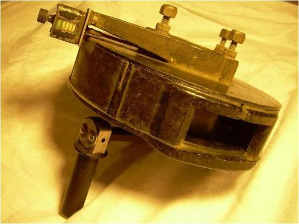
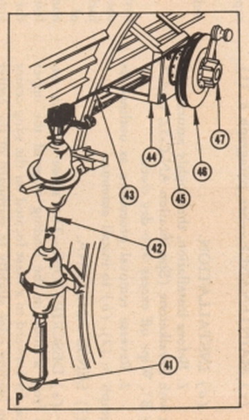
Steve, then here are #41 to #47

Image

Yves, I have never compared Sterba with British ASV MkII to answer your question and radar is out of my sphere.
So I am not skilled in analyzing their diagrams.
I don't know how long the Navy retained the Sterba and I think it was a specific Navy device on the PBY.
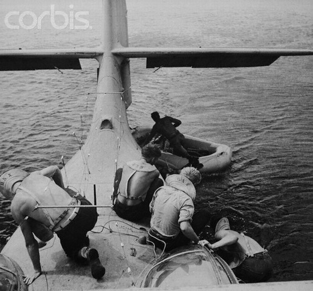
Not to say that it was not very easy when you had to walk on the hull...
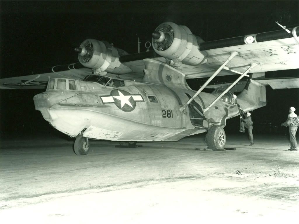
Anyhow it appears that the radar equipment was changed (obviously upgraded) on the later versions and you found Yagis on most of PBYs, Catalinas, Cansos, OA-10As.

Late Wynnum Graham sent us this historical record about DP202, the aircraft you send the picture of.

Prototype British LRASV Catalina.
 In November 1940, Air Ministry decisions were made that the prototype of PBY aircraft for Long Range ASV should be carried out in USA with the assistance of Dr E G Bowen.
By 21Mar41, Dr Bowen reported  -- He had visited CAC San Diego, with Mr Yearsley of the British Air Commission - discussions were held with Mr Learman, Assistant Chief Engineer, and Mr Meguire, Engineer in charge of Electrical Installations -- - re fitting LRASV to the PBY. CAC gave a very definite impression they were unwilling to press ahead with the work, that UK would be very lucky to get (LR)ASV aerials on the delivered aircraft until very late in the production schedule.
By the end of March 1941, this report was being acted upon in the UK. It was recognised the system would have to be fitted locally, and the drawings sent from US by Dr Bowen were distributed to necessary recipients, importantly to MAEE at Helensburgh.  Dr Bowen’s work still included wire aerials which were not favoured by his counterparts in the UK.
Early in April 1941 a meeting was held at Greenock, to examine possible fixing positions for aerials. Present were F Lt Ives of Coastal Command;  Mr Bridges of Saunders Roe (Beaumaris), in his oversight capacity at Scottish Aviation, sub-contractors to Saunders Roe;  Mr Johnson of RAE, having oversight of MAEE at Helensburgh;  and a Mr Power.
Mr Johnson, back at Helensburgh, quickly assessed the situation and sent out a signal .......... 06Apr41 – MAEE Helensburgh (Johnson)  to ACAS, MAP DCD, MAP DGAP (SI), RAE, TRE .......Catalina LRSI installation requires new type aerials. Impossible fit any existing types. Proposed new aerials require experimental work and aerodynamic investigation. Estimate 14 days for experimental work. Manufacture of TI parts and fitting can then proceed.
[LRSI is Long Range Special Installation - - - TI is Trial Installation]
Catalina Mk I, A24-2 (an Australian serial which was ferried to UK for RAF service as the result of a swap with AH534) became the MAEE Helensburgh prototype plane for LRASV.  Mr Wood of MAEE took up the electrical design/assessment work on various Yagi aerial locations - - he continued these tests through April 1941 at Helensburgh.  A search Yagi transmitter located between the wing stays was assessed and discarded, then a position forward of the wing was accepted.
While Mr Wood was working on the electrical problems at MAEE Helensburgh with mock-up aerials, Mr Bridges was at Scottish Aviation, Greenock pondering mechanical matters relating to fitting and sealing the aerials to the aircraft, as well as physical aerial design for strength of supports, etc.  From 22Apr41 Mr Wood visited Greenock by RAF power boat to discuss various arisings with Mr Bridges. 
By 25Apr41, it was announced the Catalina aerial work had reached agreeable electrical designs.  It now remained for the various aerials mechanical design and stress work to be done without upsetting the electrical parameters – primarily a responsibility of Saunders Roe, still with advisory input from MAEE.
Mr Bridges of  Saunders Roe suggested Mr Wood should re-visit Greenock to collect his (Bridges’) proposed design and take it to RAE for the stressing department to consider.  Mr Wood discussed/collected the proposed design Friday 25Apr41, then took the overnight train to London, returned Thursday, 01May41.
Catalina A24-2 was now due to move across to Scottish Aviation at Greenock from MAEE Helensburgh - was due there on 06May41 – in order that LRASV fitting may commence – All details of electrical requirements passed to Saro 6/5/41. Aerial design is proceeding and will soon be complete.
Enemy action at Greenock on 06May41 put paid to well founded plans. More serious enemy action at Greenock on 07May42 caused even further changes.  The Scottish Aviation works at Greenock was in shambles. A24-2 stayed put at Helensburgh. 
By 08May41, Mr Bridges has gone to Beaumaris with all designs and records. He left a message, suggested A24-2 should follow him to Beaumaris and be fitted there.  Mr Wood sent a signal ~ “Delay due to enemy action. Suggest work proceeds at MAEE. Request instructions.”  Next day, Group Captain Ring of MAP phoned Mr Wood. Gp Capt Ring agreed the work was to be done at MAEE, promised to contact Mr Bridges ........ later again, Gp Capt Ring phoned Mr Wood, requested Wood go to Beaumaris and persuade Mr Bridges and party return to MAEE and do the work on A24-2 at Helensburgh.
12/14May41 – Mr Wood visited Beaumaris, to arrange the programme, necessary due to enemy action at Greenock. Mr Bridges and staff agreed to return to Helensburgh on 18May41, installation to proceed with MAEE, Mr Bridges of Saunders Roe , and Mr Wood working together.
On 20May41, Mr Bridges and party arrived Helensburgh to re-commence work. A24-2 was re-serialed to DP202.  Through May and into June of 1941 work continued on DP202 at Helensburgh – aerial design, manufacture, drawings for mass production purpose etc. Internal wiring was done, connecting the components as they were completed and fitted. Yagi Homing array (forward looking) was fitted to the wings, being an adaptation of existing Wellington Yagi aerials.
20Jun41 quickly rolled round – pressure was mounting for DP202 to be put to squadron trials – wing aerials still not complete, and more ...... the standard “conversion modifications” of preparing a delivered machine for operational flying were still outstanding.  Next day however, a flight trial of three hours was done with satisfactory results on the search (side looking) apparatus.
Further work was necessary before the next flight  ........... which was over a month later, 30Jul41, no doubt largely due to the conversion modifications.  These were usually done by Scottish Aviation at Greenock, or by Saunders Roe at Beaumaris. To be done at Helensburgh was an added complication.  The Homing array test flight of 30Jul41 was successful.
DP202 was transferred on 11Aug41 to 210 Squadron at Oban for service trials, which were soon completed, such that on 06Sep41 the  Director of Communications Development advised RAE that Coastal Command has approved the LRASV system in DP202, subject to a small list of small changes.
By 27Sep41, DP202 was at Greenock, being fitted with long range fuel tanks for a demonstration tour to America, mainly to Consolidated Aircraft Corp at San Diego, where it was built – now showing its wares as the prototype LRASV Catalina.  DP202 departed Greenock 06Oct41.
After the US demonstration tour, it did service through the war with the Canadians – RCAF.  After the war, it gained another life;  departed Toronto on 17Sep46, passing from RCAF to Netherlands East Indies for military service with RNNAS as serial P200 until 14Feb52 when it was scrapped at Biak, off the northern coast of Western or Dutch New Guinea.

And Bob Romaine to remind...
As a Consolidated flightline employee, I was surprised one morning to see a British PBY-5 [FBxxx] parked outside the gate to the airfield. I was told it was
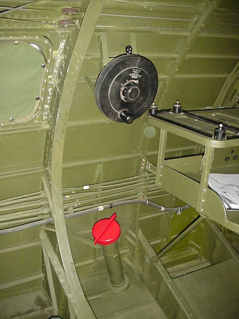
top secret and was under heavy security. I was later cleared to go onboard with company engineers to inspect this new top secret equipment,"RADAR". It had a yagi antenna permanently fixed under each wing, [coat hangers we called them], and some other antenna wires that were different. What was also quite different was a large amount of equipment, using up half of the nav table, that required the hatch above the nav table to be sealed. I was led to believe this aircraft was provided to Consolidated in order to copy the system and install it in subsequent PBYs. One thing I do remember when we removed the yagis from the wings was that there was a lot of corrosion at the point of attachment due to steel yagi and bolts being used against the aluminum skin. Our eventual "copy" was all aluminum.
I had a look at the plane's log and observed that this plane had spent most of its time between flights at the bouy and only made it up the ramp about once a month. Heavy utilization.

_________________
J-Chris.
The PBY Enthusiast.


Top
 Profile  
 
 Post subject: Re: PBY-5/5A antennas
PostPosted: Mon Mar 31, 2014 12:04 am 
Offline
User avatar

Joined: Wed Oct 12, 2011 2:55 pm
Posts: 10
Location: France
Yves I may have found an answer in this book :
Boffin: A Personal Story of the Early Days of Radar, Radio Astronomy and Quantum Optics
Par R. Hanbury Brown
Quote:
What I understand from it is that the "Sterba curtain" + 2 Yagi's under the wings was the early antennas configuration for the radar. Could it be that later on the Sterba-array was not used any more, but 4 Yagi's under the wings or on both sides of fuselage (as in the scheme above) became the standard equipment?

Try the following link and read from page 24 onwards.
http://books.google.fr/books?id=jWIe46x13p0C&pg=PA25&lpg=PA25&dq=Sterba+vs.+ASV&source=bl&ots=8PF6q6R5yw&sig=V3KO3yJpnAe3Xg5IthNCTdt-ipQ&hl=fr&sa=X&ei=G1Y4U5K8KKeY1AX7uoHoCw&ved=0CIYBEOgBMAk#v=onepage&q=Sterba%20vs.%20ASV&f=false

_________________
J-Chris.
The PBY Enthusiast.


Top
 Profile  
 
 Post subject: Re: PBY-5/5A antennas
PostPosted: Mon Mar 31, 2014 10:56 am 
Offline
User avatar

Joined: Wed Oct 03, 2012 12:51 pm
Posts: 42
Location: GTA, Canada
J-Christophe wrote:
Yves I may have found an answer in this book...

Jean-Christophe, thank you very much for your reply. I'll check the book - I hope I'll find some time today! :)
BTW when posting the last photo of the Catalina with 4 Yagi antennas I didn't think too much of the differences between the US and the British radar equipment - my bad! This was just one of the good photos I could find. I've seen USN PBY's with the same configuration or with even more receiving and transmitting Yagi-arrays too. But the good side of my "mistake" was the plenty of additional information you posted! Merci!
Best Regards!

_________________
Yves Marino


Top
 Profile  
 
 Post subject: Re: PBY-5/5A antennas
PostPosted: Mon Jul 20, 2015 4:09 am 
Offline

Joined: Mon Jul 20, 2015 3:17 am
Posts: 1
Hi Folks,
Been searching around for info on Coastal Command Catalina radar and aerial configurations, and came across this topic.

Something I may be able to clear up. The main yaggi's are of course the search radar, but the other smaller pointing straight forward ones are for radar beacon navigation.
It was realised that due to the high(er) frequency of radar energy it would travel further. As CC were flying many miles over a featureless ocean, relying only on radio/chart/shot/calc of the navigator, it was found that an omnidirectional beacon transmitting on the radar frequency could be picked up by the search radar from a long distance. This was refined by using dedicated nav yaggi aerial(s). If you look at later ASV 1 or 2 equipped Sunderlands the nav beacon yaggi is usually raised directly over the cockpit or sometimes on either side of the nose.

https://www.google.co.uk/search?q=short+sunderland+aerials&source=lnms&tbm=isch&sa=X&ved=0CAcQ_AUoAWoVChMIiv7ms6npxgIVTFYUCh1LtQCn&biw=1680&bih=896#imgrc=gyjfwl5JkT6SnM%3A

Or https://www.google.co.uk/search?q=short+sunderland+aerials&source=lnms&tbm=isch&sa=X&ved=0CAcQ_AUoAWoVChMIiv7ms6npxgIVTFYUCh1LtQCn&biw=1680&bih=896#imgrc=iC254ANrMfwCWM%3A

Shessi

Tried to insert images, no go. Am I missing something here?? Thanks.


Top
 Profile  
 
Display posts from previous:  Sort by  
Post new topic Reply to topic  [ 9 posts ] 

All times are UTC - 5 hours


Who is online

Users browsing this forum: michael luther and 37 guests


You cannot post new topics in this forum
You cannot reply to topics in this forum
You cannot edit your posts in this forum
You cannot delete your posts in this forum
You cannot post attachments in this forum

Search for:
Jump to:  
Powered by phpBB® Forum Software © phpBB Group